
Last Updated: 5th March 2021
UltraHDMI
Installation Guide
Table of Contents
Overview
This document will show you how to properly install UltraHDMI into a donor Nintendo 64 console.
Each “install kit” consists of the following:
- PCB
- Flat flex cable (FFC)
- Two different pieces of foam
- Label with your installer code for N64 case

Total time for installation can be as short as 10 minutes. By batching up several consoles and doing each step across all units, you can save even more time.
However, plan for the first install to take at least an hour while you figure things out.
CAUTION!
Both the N64 board and the HDMI board are static sensitive. Always stay electrically grounded – proper ESD handling is mandatory to prevent permanent internal damage.
Tools
Good quality tools will make the difference between a long, painful and potentially non-working install – and a painless success. Do not use any non-rosin flux.
Soldering Iron
$20 “firestarter” irons do melt solder, but for SMD soldering it is much more predictable and less destructive to use a temperature controlled iron.
I use the Hakko FX-888D, but an older 936 or Chinese clone like the Aoyue 937 will probably suffice.
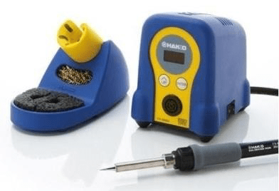
The tip shape also affects how the heat spreads and the amount of solder you can “carry” on the tip itself. Pointed tips aren’t useful for drag soldering.
Small chisel tips are the easiest to use. Many Aoyue iron handles will accept the higher quality Hakko tips.
Recommended: Hakko FX-888D or better
Will also work: Any temp-controlled iron with a tip suited for SMD
Do not use: crusty old irons.
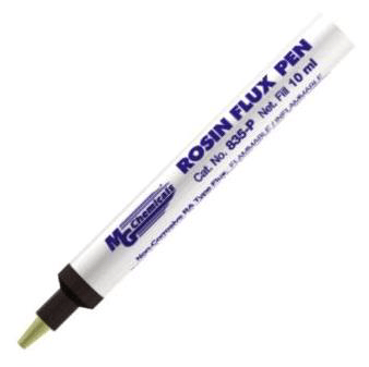
Flux
Makes drag soldering possible, and turns lumpy old solder joints into smooth shiny ones. It’s essential for soldering the flex cable and any bare copper. In fact, “flux core” solder rolls have a small amount of flux embedded into the center of the wire, so you get nice joints when adding new solder.
Flux does burn off and go away if you heat it for more than a few seconds. When using a connection’s existing solder like for the RCP and FFC, a small amount of flux helps the solder wick and flow where it should, making its liquid surface tension work for you.
Stay far away from any flux that requires a complete heat cycle to become fully “activated” – like water soluble and no-clean. Many so-called “noncorrosive” fluxes are in fact extremely corrosive unless you subject the entire work piece, PCB and all, into a full reflow oven cycle. While this isn’t a problem for an assembly shop making a new product, it’s not practical for rework. You may find that these turn copper traces into white chalky powder and ruin the PCB after just a few weeks. It is also not possible to fully clean these agents from the joint. Even a “clean” solder joint may come back to fail months later.
Rosin flux, while it requires clenaup with 99% isopropyl alcohol, is never corrosive and safe to use.
Recommended: MG Chemicals 835-P (also available in liquid-only form)
Will also work: Any rosin flux
Do not use: Any no-clean or water soluble flux
Cutting Tool
Any Dremel-like tool works here, with a small cutting bit. Doesn’t need to be very big. This is just for cutting out the bulk of the HDMI slot.
I use a Dremel Stylus which is now discontinued, but Genesis also sells a cheaper version that probably works similarly.
Avoid grinding wheels, and go for an end mill-type bit instead.
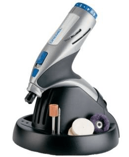
Recommended: Dremel
Will also work: Genesis GLHT72-65
Needle File
For finishing the slot to make it sharp and rectangular, you’ll need to file it by hand. You need to make sharp corners, so only a rectangular needle file is necessary. Find one with cutting edges on at least 3 sides, so you can get it into the corners.
Chinese-made files work, but are less effective and won’t give as sharp corners.
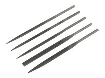
Recommended: Grobet or any Swiss rectangular file
Other Tools
You’ll also need the following:
- Xacto/hobby knife
- Leaded solder (rosin core only, do not use no-clean solder)
- Old toothbrush
- Kapton tape (optional)
- Solder wick (for last-ditch clean and start over)
Technique
Drag Soldering
This method is the fastest and easiest way to solder lots of close SMD pins – and when using a wider flat/chisel tip, is the only way to get it done.
Liquid solder will bead up on the metal it touches the same way water beads up on smooth glass. Flux retards oxidation and so allows a meniscus to form. Without flux, solder becomes oxidized and impossible to work with.
For new connections where there is no existing solder, you can load some onto the iron tip. Otherwise, the existing solder on the joint contributes to the total solder that can be distributed along the pins, so don’t add to it – only add some flux.
To drag solder, add a small amount of flux, some solder to the tip if necessary, and press the iron onto the connection, moving the iron down the pins allowing surface tension to make each connection a nice bead. Solder wick can be used to later remove any residual shorts.
Disassembly
Take Apart the Case
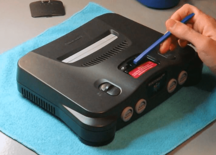
1. Remove Expansion Pak cover.
Carefully peel off warning sticker and store on wax paper to put back later.
2. Leaving pak in place, flip over the console.
Remove the (6) 4.5mm security screws with a Gamebit tool.
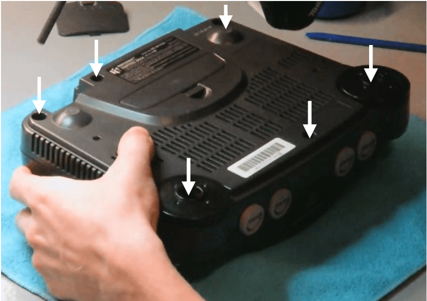
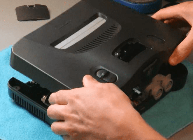
3. Set screws aside and lift apart top case half.
Jumper/expansion pak will come out as well.
Remove Motherboard+Shielding
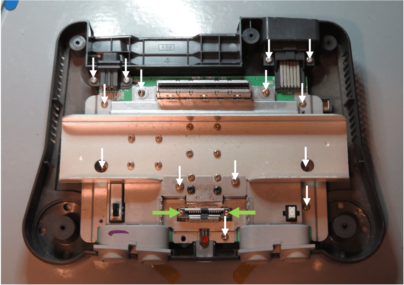
4. Remove the following (16) screws.
Note that there are 2 different head sizes, and 5 unique kinds of screws.
It’s not necessary to remove the screws in the middle, they only hold the heat spacers on.
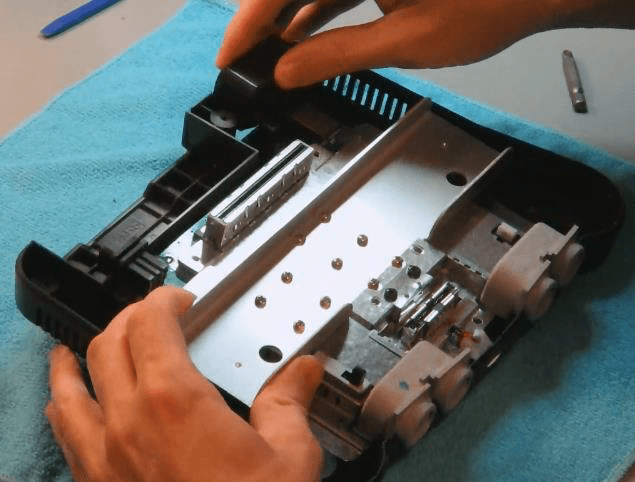
5. Lift out entire motherboard assembly.
Remove the heatsink and top shielding, setting everything aside.
If the heatsinks are stuck to the chips you should lift up the metal by the edge closest to the cartridge port and pry upwards.
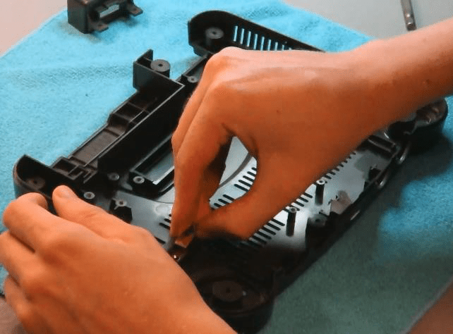
6. Remove the (2) metal retainer clips.
Remove the power LED lightpipe.
Cleaning
Most consoles will contain 20 years of dust and dirt/hair inside. It’s not strictly necessary to clean everything, but it does improve cooling as well as leave a positive impression on the overall installation.
It is always necessary to clean out the upper-right area inside the case of any dust or hair where the HDMI PCB sits. During normal operation the HDMI PCB will get even slightly warmer than the N64 itself, so airflow is crucial.
For a thorough cleaning, strip down both case halves, removing the power/reset switches, cart dust flaps, and all covers. Reset switch failures are typically just due to hardened grime in the switch recess.
An old toothbrush with an extremely weak soap/water solution will do wonders for removing built-up dirt, especially in the embossed plastic text on the case.
Cutting the Slot
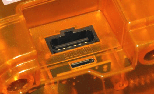
The PCB sits inside the console right under the A/V port. To expose the mini-HDMI connector you will need to carefully cut out a small part of the bottom case.
The slot must fit the HDMI connector snugly, without any roughness or extra gap. The plug’s strain relief is provided by a snug fit in the case – which is lost if the hole is too rough or oversized.
Mark the Cut Position
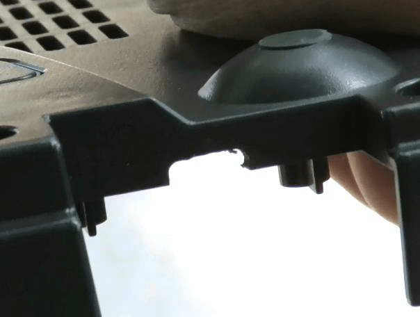
7. Lay the HDMI PCB in the case, noting where the HDMI connector hits the case plastic.
8. Use an xacto knife to mark lines parallel with the edges of the connector.
9. Mark a horizontal line for the bottom of the cut. The top of the connector will sit flush with the top of the plastic.
Cut It Out
10. Using your dremel, carefully cut out just up to the marks you made. Don’t hit the lines you made, stay back a bit.
File the Rest
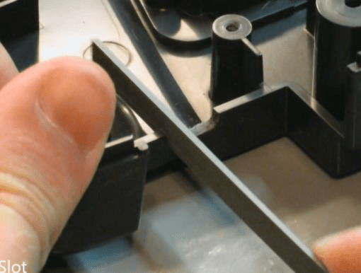
11. File the rest of the way up to the guide lines.
Maintain a constant 90 degree angle to the case. Most files will only cut on the push stroke.
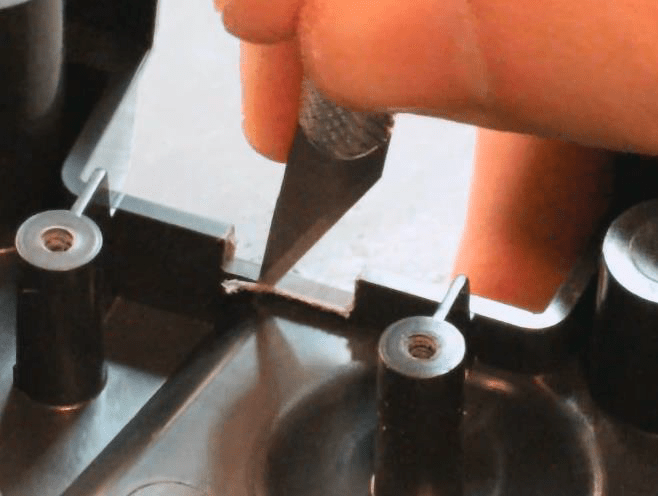
12. Cut the swarf off with your xacto knife.
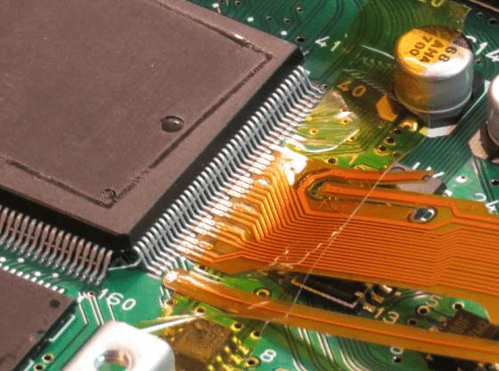
Soldering the FFC
This is the most critical part of the install.
RCP Connections
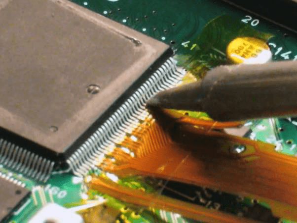
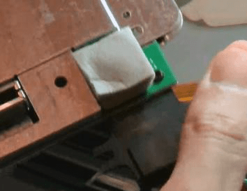
13. Clean the RCP pins and surrounding area with a dry, soft rag to remove all dirt, hair and foreign contaminants.
14. Butt the flex cable up to the ends of the RCP pins. The bottom-most FFC pad should be on pin 6 of the RCP. So, the FFC will be located just above the bottom white dot on the chip.
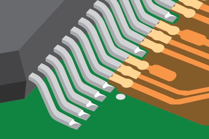
15. the FFC end plated pads should be up against the chip pins, but on top of the small solder area on the N64 motherboard.
It may help to hold the FFC in place with some kapton tape while you solder.
16. Apply a small amount of rosin flux only.
If using a pen, wipe over the bare contacts like a sharpie.
17. Clean your iron tip off completely with a damp sponge.
Add an extremely small amount of solder – just barely touch the tip to the solder roll end.
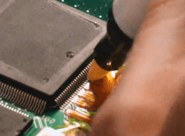
18. Start at the top, with the iron at about a 30-40 degree angle from horizontal.
Pres the tip down against the end of the pins, and draw it outwards/back towards the FFC.
Move a couple millimeters down and repeat.
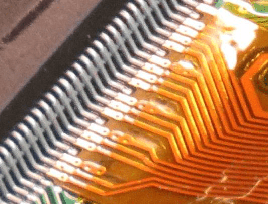
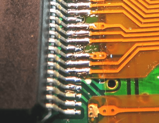
19. Ensure that each joint is shiny and bridges the RCP pin to the flex cable. There should not be any breaks, or any shorts with adjacent pins.
Run the iron over any pints that might still have shorts or have inconsistent soldering.
After several seconds of continuous heat, the flux may burn off, so add a small amount more if that happens.
Do not let the iron linger too long on any pin – the FFC, like all circuit boards, will eventually come apart under extreme heat.
Power Connections
20. Bend out the two FFC ears and fold them over, so that they reach the legs of the two capacitators.
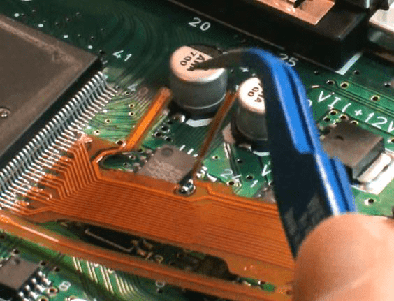
21. Tin the ends of the FFC pads – apply a bit of solder while heating with the iron.
22. Dab a small amount of flux onto the leads of the capacitators.
23. Solder the ends down to the capacitator leads.
You may have to wait several seconds to heat up the joint and get a proper reflow.
This completes the 3.3v/5v supplies.

PIF Connection
The last connection is to the controller 1 I/O line.
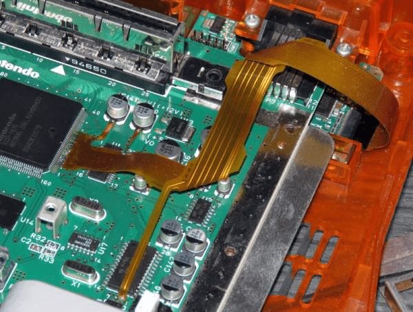
24. Bend the FFC so that it makes two right angle bends.
The PIF connection part of the FFC will snake downwards.
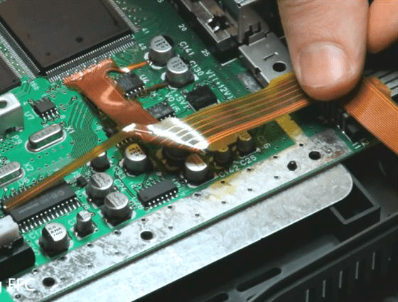
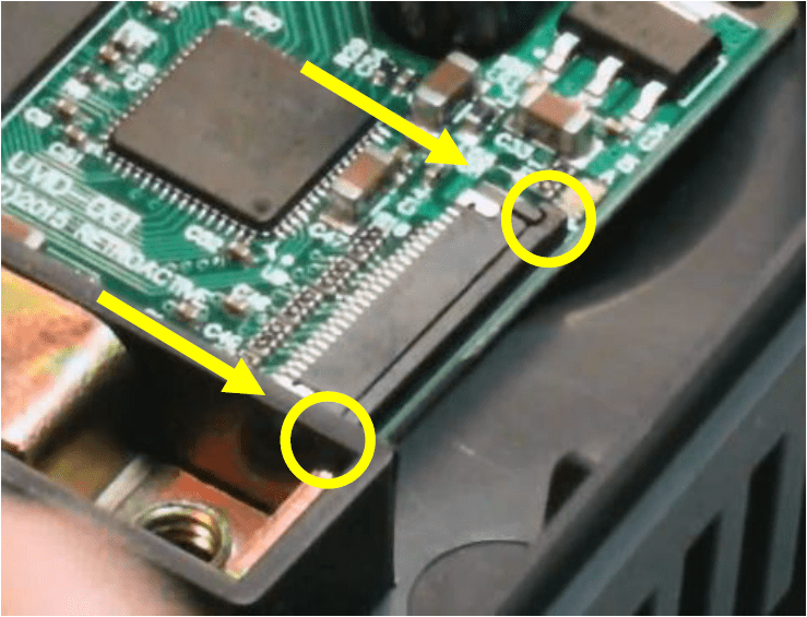
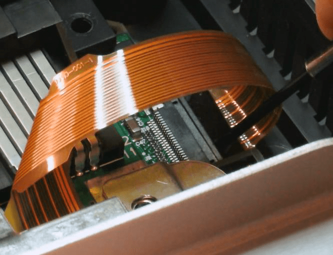
Depending on what revision of N64 you are servicing, you will have to choose 1 of 2 possible points. Look at the very top of the motherboard above the cartridge slot to see which revision it is.
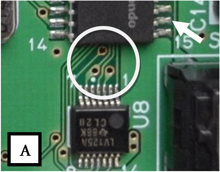
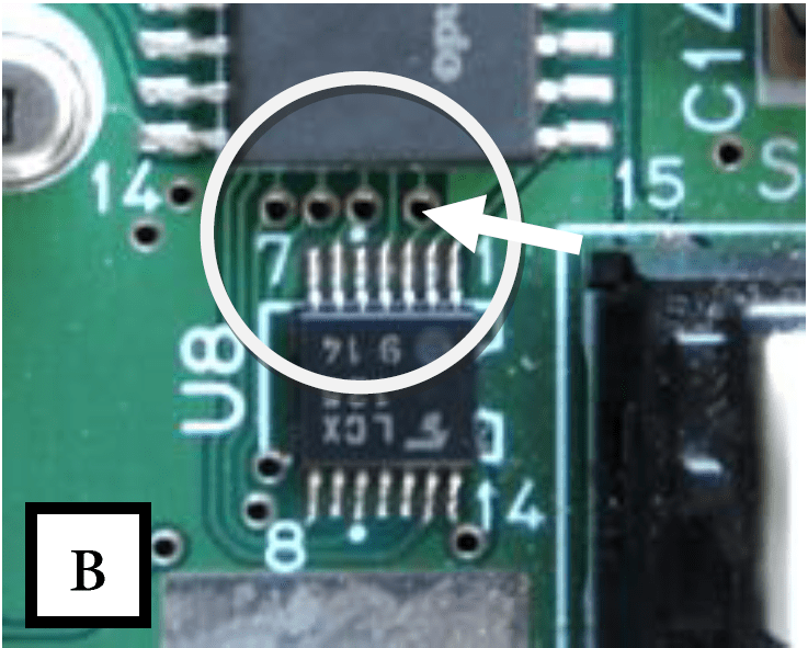
Compare the two pictures below near your board’s PIF.
Earlier revisions: Generally NUS-CPU-01 to 05. If you see the via arrangement matching this exactly, you can solder to pin 16 of the PIF as pointed to by the arrow.
This will be the case for the vast majority of consoles.
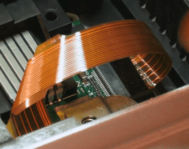
Later revisions: Generally NUS-CPU-06 to 09. The attachment point is the via referenced by the arrow. Scrape off the green soldermask from the via by carefully scratching with your xacto knife at a shallow angle to the PCB. Then apply flux and tin the via. Attach the flex end.
Do not simply attach to PIF pin 16. This will allow polled reads to be snooped but the user won’t be able to bring up the non-game setup, potentially locking them out of the OSD.
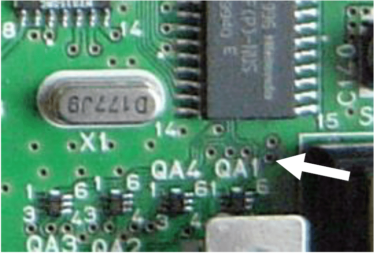
Any other PCB layout: Some later PAL units have different controller driving circuitry. Attachment point is via next to QA1 silk. For any other case, contact me and we’ll figure out where it should be attached.
Do not attach to PIF pin 16.
In-Game Reset Connection (Optional)
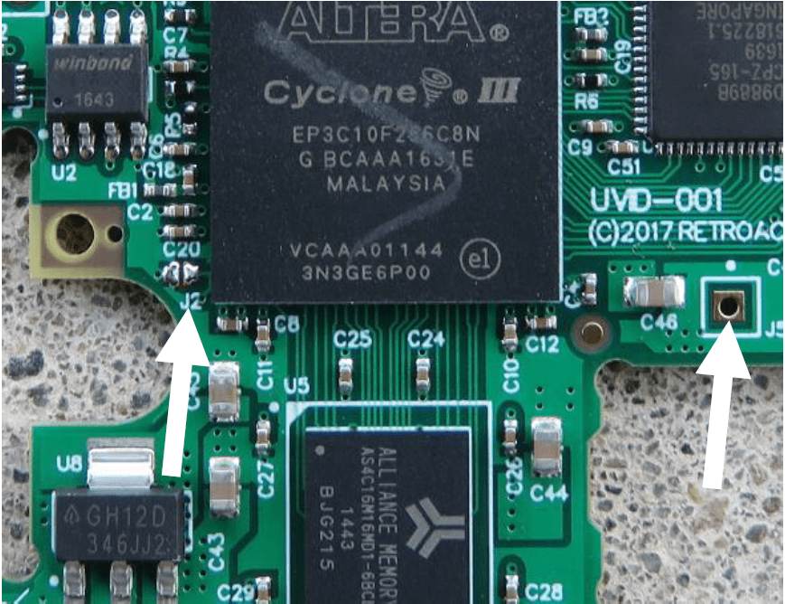
On the board, jumper “J2” is a jumper that restores factory defaults when shorted – in case the OSD cannot be used.
Starting with firmware 1.06, the debug jumper has been repurposed into a solder point for the In-Game Reset. As it currently requires installing another wire, it will not be provided support past this install guide.
The option must be enabled in the menu first. Change the “DISABLE HOTKEY” setting to either “NO+IGR” or “YES+IGR”.
When the key combination (Z+R+A+B+Start) is pressed, the pad is electrically driven low for 100-200ms and then tri-stated. Because the N64 reset button is active low, wiring this pad to the reset switch will cause a soft reset.
If this feature is desired, install a single additional wire running from PIF pin 27 to the right side of the solder jumper J2 denoted by the arrow. Be careful not to cause a solder bridge on that jumper, or to damage the large IC next to it. Or, instead of PIF pin 27, you may solder to the active pin on the bottom of the reset switch itself.
On UltraHDMI boards produced with a batch code of ’10’ or greater, this connection is duplicated near the right for more convenient soldering.

Keep in mind that the game must be polling the controller for the key combo to be detected. If a game has crashed or hung, it will still be necessary to use the real Reset button.
As an interesting side effect, the N64’s Reset button will now cause a factory reset to the HDMI board if it is pressed while turning on the console.
PCB Placement
Install Foam
25. Remove the backing from the black dense foam and place it on the bottom of the PCB inside the white guides.
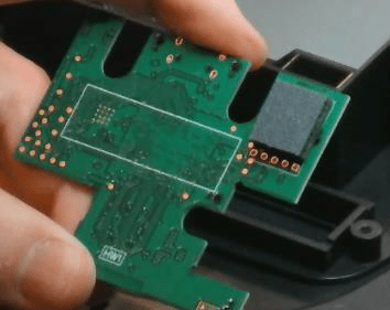
26. Put the PCB in the bottom console shell.
Make sure it lays completely flush with the case and the HDMI connector doesn’t stick out above the case parting line. Dust, plastic particles or foreign material must be removed.
Optionally, you can leave it outside and connect the flex cable to it first, then carefully place the PCB while it’s connected.
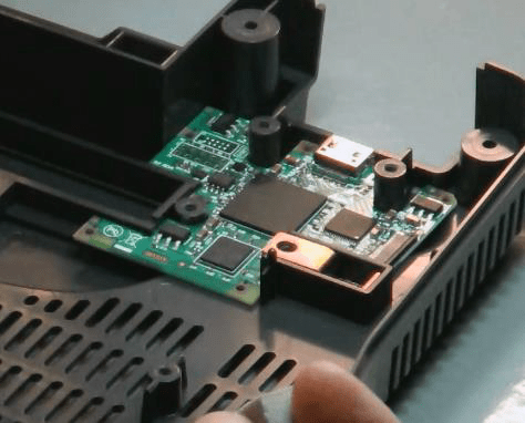
27. Attach the light, thick foam to the bottom of the console’s A/V connector. This applies downward pressure on the HDMI PCB to keep it from moving.
Plug in the FFC
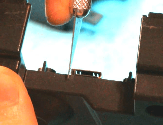
28. Using a very small screwdriver or a toothpick, open up the connector.
Apply outward force on each connector ear. It’s somewhat easy to break the connector with too much force, so alternate sides.
29. Insert the FFC end into the connector with the gold contacts facing down.
If the connector closes up it’ll be impossible to insert the FFC, so make sure it stays open.
30. Close the connector by carefully pushing horizontally.
The connector can easily bend upwards and break off. Again, this may be easier to do before placing the board in the case.
31. Using at least 91% isopropyl alcohol or flux cleaner, use a microfiber rag to clean dried/excess flux from the RCP flex connection and other soldering points.
Testing the Installation
32. Test the console with a game plugged in. Leave HDMI unplugged first.
If you used any liquids/water to clean the internals, make sure it’s dry before powering on.
The PCB has a bright red LED that tells what the board is doing – refer to the Troubleshooting section to see the table.
33. Plug in mini-HDMI cable to powered-on TV. Check that the throbbing LED turns off when you do so.
34. Bring up the OSD with the hotkey: L/Z + Dpad right + C right + R trigger.
35. Open up the menu: [ABOUT…] > [SELF TEST…]
36. Confirm there were no additional shorts or open signals (PROBLEMS FOUND: 0). Make sure you are using a game producing audio so that the audio lines are excercised as well.
This is important because some pins are non-critical – any short will result in loss of graphic fidelity while not being immediately obvious.
37. Turn off, remove the game cartridge, and power back on. You will see a black screen but you should still be able to bring up the OSD with the hotkey combo again. This exercises the alternate controller polling.
Re-Assembly
38. Put the console back together.
Remember the metal retainer clips and LED lightpipe.
Do NOT use an electric drill or impact driver to tighten the screws.
They will shear off the plastic screw mounts because of the large inertia. Some drills have an optional low speed gearing which will work – you could also use a slow electric screwdriver.
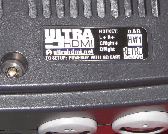
39. Place the exterior label in one of the recesses on the bottom. Contains a two-letter installer code that lets your customer know you did the install.
In this example, it’s marked “0AB” – “AB” is the installer code.
40. Done!
Troubleshooting
Virtually all failures will be due to incorrect soldering of the flex connection. If you are able to bring up the OSD on HDMI, run the self test and see what problems are reported.
The HDMI board has a bright red LED visible through the vents on the side of the console useful for debugging:
| HDMI Board LED | What it Means |
|---|---|
| Dimly lit, solid | FPGA unable to configure, wiring problem. May also happen if firmware upgrade fails. |
| Very fast blinking | PLL clock generators stuck locking. Check wiring, specifically 5v supply. |
| Bright, steady on | Upscaler CPU started but failed initialization. |
| Very slow throbbing | Normal operation with no HDMI sink plugged in. |
| Completely off | Normal operation with HDMI sink plugged in and transmitter ON. |
| Symptom | Cause |
|---|---|
| N64 does not turn on – no LED on console | Short somewhere between 3.3v and GND. Correct the soldering fault. Power brick may have tripped PTC fuse as a result, use another brick or unplug and wait a day. |
| N64 turns on, but no analog video output | RCP flex may have adjacent pin shorts. |
| TV shows “Mode unsupported” | Reset factory defaults: Hold A + B + Z + Ltrig + Rtrig while powering on. 720p (FW 1.06+) or 480p will be set. |
| No audio over HDMI | Open HDMI SETUP menu and confirm INTERFACE displays HDMI. If so, there is a problem with the soldering on the lower pins of the FFC [15-18]. If it displays DVI, the monitor was detected incorrectly. |
| Unable to bring up OSD with hotkey | “DISABLE HOTKEY” option may be set. Remove any game cartridge, activate hotkey, and clear the option. If a game is running, the game must be reading the controller for the OSD to come up. |
| Flickering red fringes on image | Usually due to poor HDMI cable quality. Try another cable. |
| “Mode unsupported” when DIRECT MODE: YES+SYNC is selected | Some TVs are not compatible with this mode. Disable direct mode or, if OSD is inaccessible – reset factory defaults per above button combo. |
Pin Mappings for FFC and Self Test
Pins are labeled starting with Pin 1 at the top and increasing downwards. RCP pin 6 corresponds wit last FFC pin 18.

Please note that the built-in self test can only detect connection errors while video and audio are being generated – such as a game running. False positives are normal and numerous otherwise.
Examples:
- All black or all white may cause spurious PIN8/9 error.
- Any homebrew that does not initialize audio will show spurious PIN17/18 due to an inactive audio clock.
- If null audio sample is produced (usually in the first few seconds) then PIN17 will appear to be stuck low.
Self-testing may not be able to detect some types of problems such as high-impedance shorts or quick intermittent shorts.
Note About Removal
De-soldering the FFC from the RCP can be easy, but takes caution as the flex PCB pads can be easily damaged. Unless you have a good deal of experience it’s more likely the FFC will be ruined in the process.
Start at the top with the iron and gently peel up while heating the joints. Do not apply excessive pressure. Reflowing the RCP pins afterwards with a small amount of flux and IPA cleanup is a good idea.