Last Updated: 5th March 2021
GDEmu Installation Manual
Table of Contents
All you will need to install GDEMU is one PH#2 screwdriver.
Before you start
Make sure your Dreamcast is a VA1 model. The best way would be to disassemble it and read the description on the mainboard, next to pad ports. Another good method is to check the single digit in a circle, next to the region designation on the back sticker:
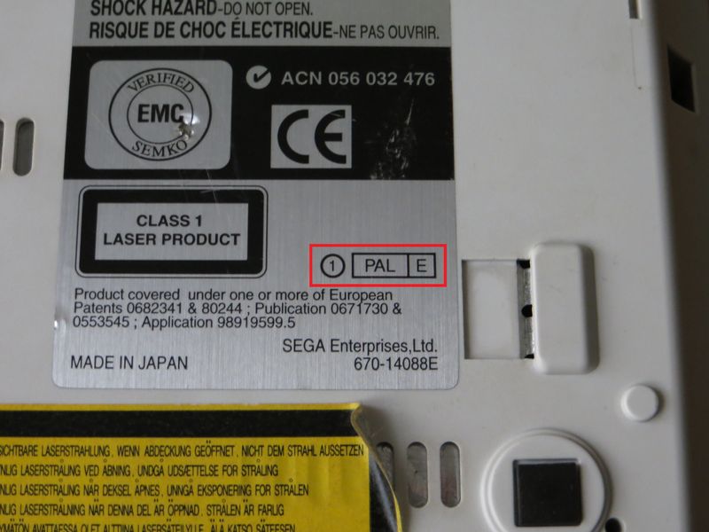
If it says “1”, you have a VA1 model. You can further confirm that after removing the upper cover, the GD-ROM drive assembly should be stamped with “3.3V”.
Installation instructions
Text-only for now, pictures will be added later. Please follow the steps outlined below, do not use force – especially when plugging GDEMU into Dreamcast motherboard – to avoid any damage.
- Disconnect all cables from the console
- Remove the disc from the drive and close the lid
- Detach modem add-on, place the console upside-down on a firm surface
- Remove 4 screws located in the corners using a Phillips PH#2 screwdriver
- Hold the console by sides with both hands and carefully rotate it to an upright position
IMPORTANT: Make sure the now unscrewed upper cover does not fall. It holds down part of the GD-ROM drive assembly, which might become separated and pull/damage the ribbon cable.
- Lift Dreamcast’s upper cover and place it aside
- Remove 3 screws holding down GD-ROM drive
- Gently pull the drive up to separate it from the mainboard, then store it away
IMPORTANT: Do not twist, it takes only as much force as a typical HDMI connector to remove the GD-ROM drive. Keep the drive assembly upright at all times. Store it in a clean plastic bag, perhaps bubble-wrapped to provide extra protection.
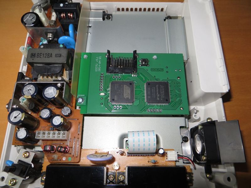
- Insert GDEMU in place of the drive, use your fingertips to make sure the socket is aligned properly before you try to push it down
2014-05-29 update for GDEMU models with screw mount
These models come with 3×20 metric screw with Pozidriv PZ1 head, its thread might not fit the hole perfectly and thus be somewhat difficult to install. You can replace it with a non-metric screw provided it has exactly the same dimensions.
IMPORTANT: Do not replace the provided screw with a longer one. Do not attempt to install the screw without PCB and sleeve in place. Otherwise, the screw might go deep enough to reach and damage the console mainboard.
A simple way to make sure the sleeve aligns properly with the hole and stays that way:
- Put the sleeve standing over the screw hole, make sure it’s well centred
- Hover GDEMU over the mounting area, align the PCB hole with the sleeve before you gently put it down, and do not push the connector in yet
- Drop the screw into the hole in PCB to make sure the sleeve won’t move away
- Now push the GDEMU down to sit it properly, and then finish by screwing it down
That’s it, you’re now good to go. Do not turn Dreamcast upside-down with GDEMU inserted if it’s not being held down by a screw. I strongly suggest putting the upper cover back to avoid electric shock and/or injury, or damage to console internals or GDEMU. No need to screw it back on though. Modem add-on can be now plugged back in if you wish. Read Operation.
External buttons
You can solder wires to extra buttons (to be mounted directly in the case, for example) by yourself. See the figure below:
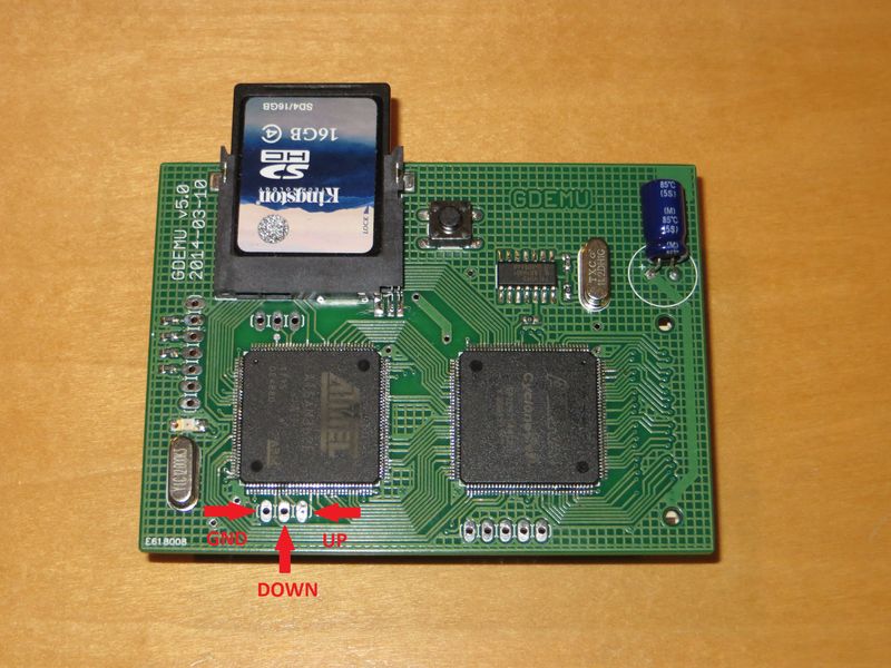
From left to right: GND (common ground), DOWN input, UP input. You can solder both or just one of them. Connect the buttons to GND on one end and chosen input on the other.
IMPORTANT: Certain early v5 PCBs will have a wire on the back soldered to UP input. You can still use this solder point for your own wires, just make sure not to desolder that original one or else the button on the PCB will stop working.
Remote
If you got remote PCB with your GDEMU you will need to assemble it yourself. The choice of having only LEDs there, or only buttons, or both, is up to you. Part list:
- 2x TACT button, NO/ST
- 4x 330 ohm 0603 resistor
- 4x 1206 LED
You can use any LEDs you like but keep in mind that blue, white, and some of the bright greens require about 2.5V to work. The resistors will need to be smaller value, though due to being brighter in general even 330 will do fine. Typical red, yellow and green LEDs need 1.5-1.7 volts. If you do change resistors make sure to limit the current to sane values – 1-5mA. 10mA if you really want super bright.
LEDs are arranged in common-anode setup. Use the 3.3V line provided by GDEMU to power them. If in doubt (the markings can be sometimes confusing), solder one down and see if it works.
OLED screen
These screens are popular now and this was a frequently asked feature so GDEMU can now use one. You’ll need:
- 128×64 pixels screen configured for SPI interface
- some wires
The wires must be soldered on the GDEMU side (or you could solder 90-degree gold pins there) and connected as on the picture below:
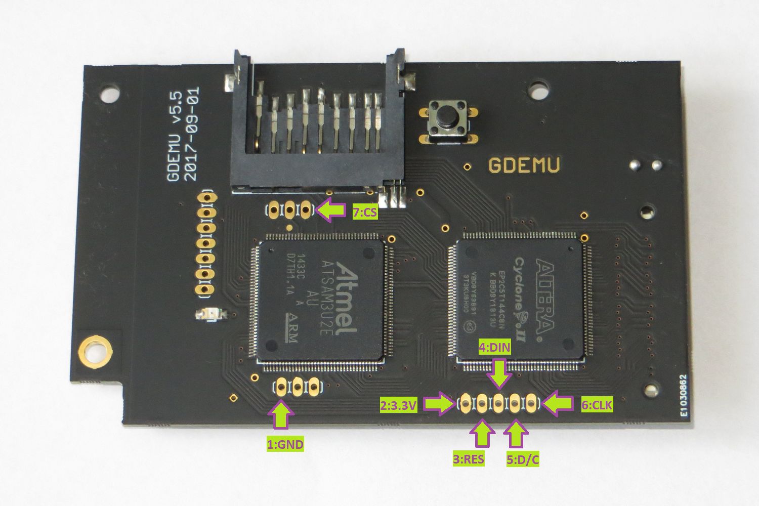
That is:
- GND – ground connection
- 3.3V – power, often marked VCC on the OLED side
- RES – reset signal
- DIN – data in
- D/C – data/command signal
- CLK – clock
- CS – chip select
NOTE: These solder points on GDEMU are also used for the older “remote” PCB (see above) with LEDs and buttons. These will still work, though you might notice short bursts of LED activity when the OLED is updated. In fact it is possible to have both the remote and OLED connected at the same time.
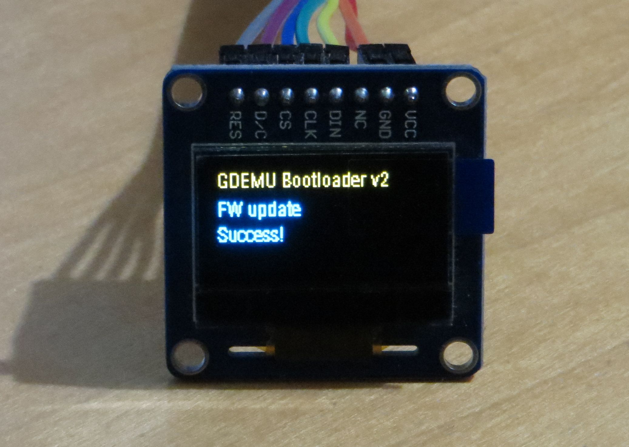
The screen itself can be single-color or have 2-color split. Here’s an example of what split-color OLED output looks like: