
Last Updated: 5th March 2021
DCDigital
Installation Manual
Table of Contents
DCDigital Internal Installation for VA0 & VA1 Dreamcast
Disclaimer
This kit is for advanced installers only. This document assumes you know how to take apart the Dreamcast with basic tools as these instructions will not be included.
This kit uses Zero Force Flip Lock Insertion FFC for the Flex cable. FFC connectors are fragile and can be broken easily if care is not taken.
Please review the installation video. Both the video and written instructions follow the same procedure.
Common Questions
Does DCHDMI work with X installed or removed? Yes, DCHDMI works will ALL known hardware mods. 12V removal/bios/sd-card/ODE/overlock etc.
It is recommended you go over the settings summary before starting the install procedure:
The Kit includes
- Main PCB
- Flex Cable
- Self Adhesive Backer
- 2x M2x8mm Screws
- 2x M2 Nuts
- Wifi Antenna
- Drill Block Guide
Items required
- Temperature Controlled Soldering Iron
- Flux
- Solder Wick
- 99% Isopropyl Alcohol
- Multimeter
- Side Cutters
- 3/64 Drill Bit
- 5/32 Drill Bit
- Drill
- Small Square File
- Small Flat File
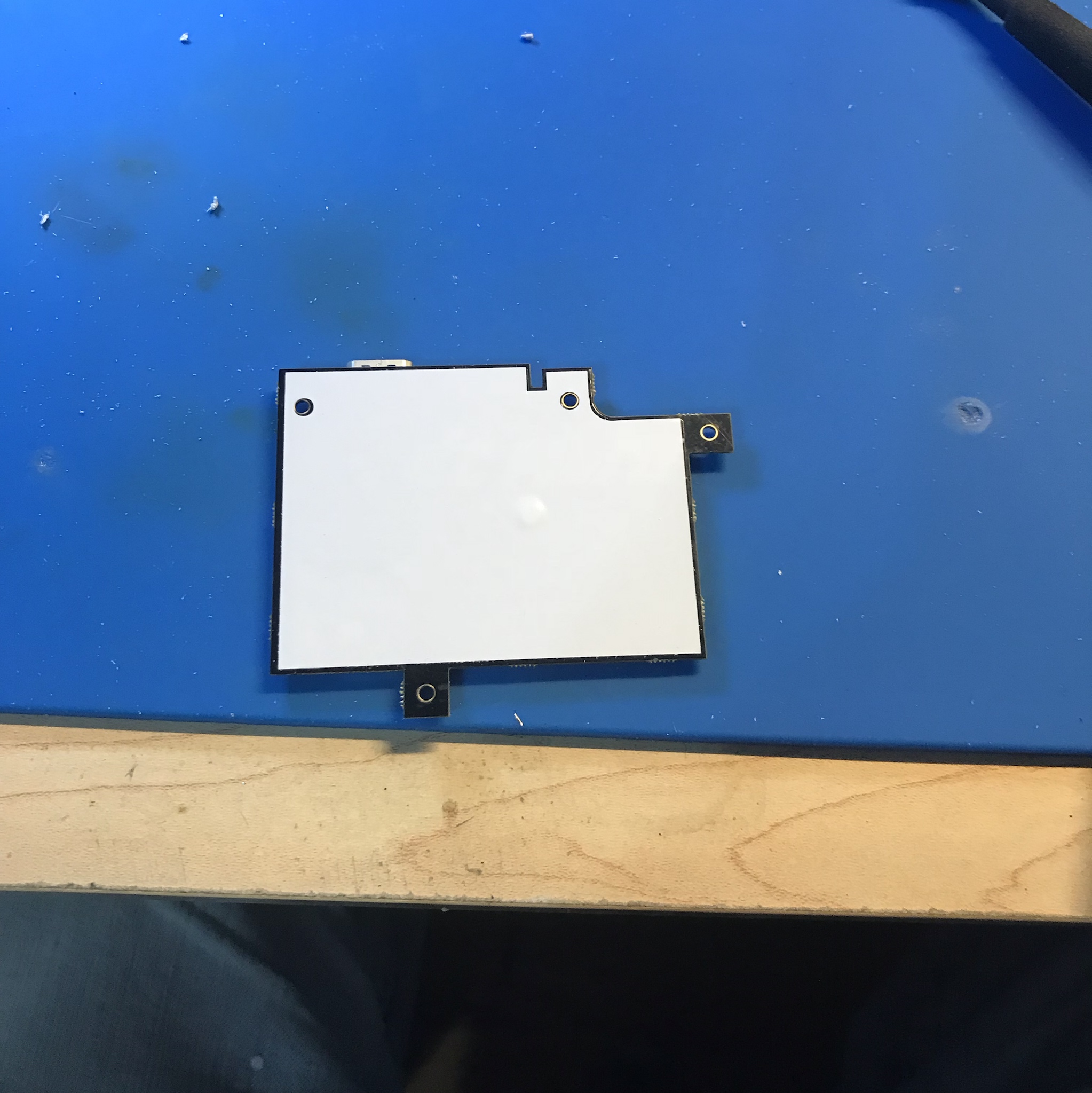
Step 1: Install Adhesive backing material
Check for fit, some backings have some overage. If yours is too large, just trim down with scissors to size. Peel off backing material paper and apply to the back of the HDMI board.
Go slow and try to align the holes.
Step 2: Mounting the HDMI board
This is tedious, take your time, you need a good fit on the HDMI connector.
Disassemble the Dreamcast, so the motherboard is free.
Keep track of the thermal pads, there are some on top and bottom of the motherboard.
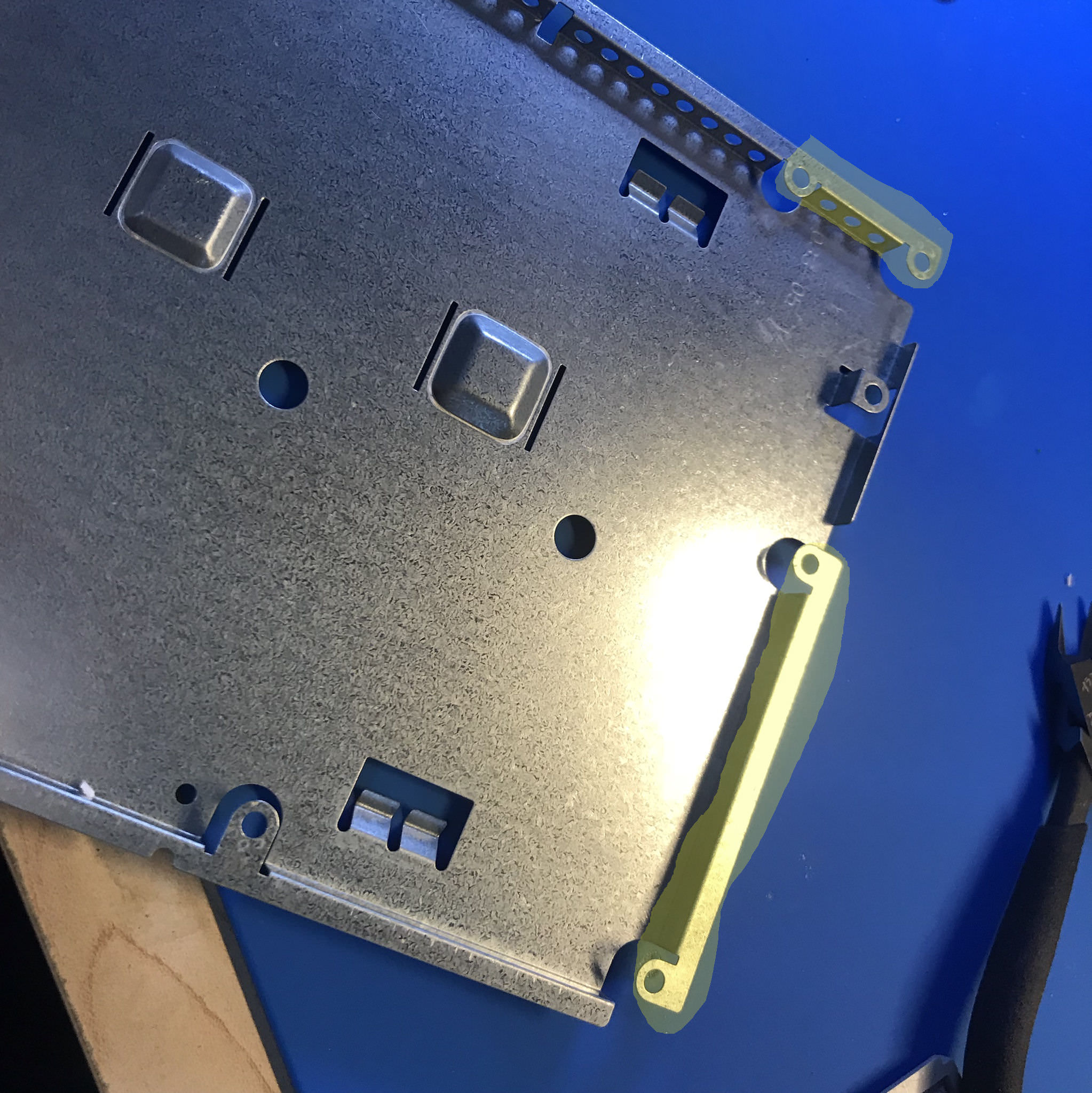
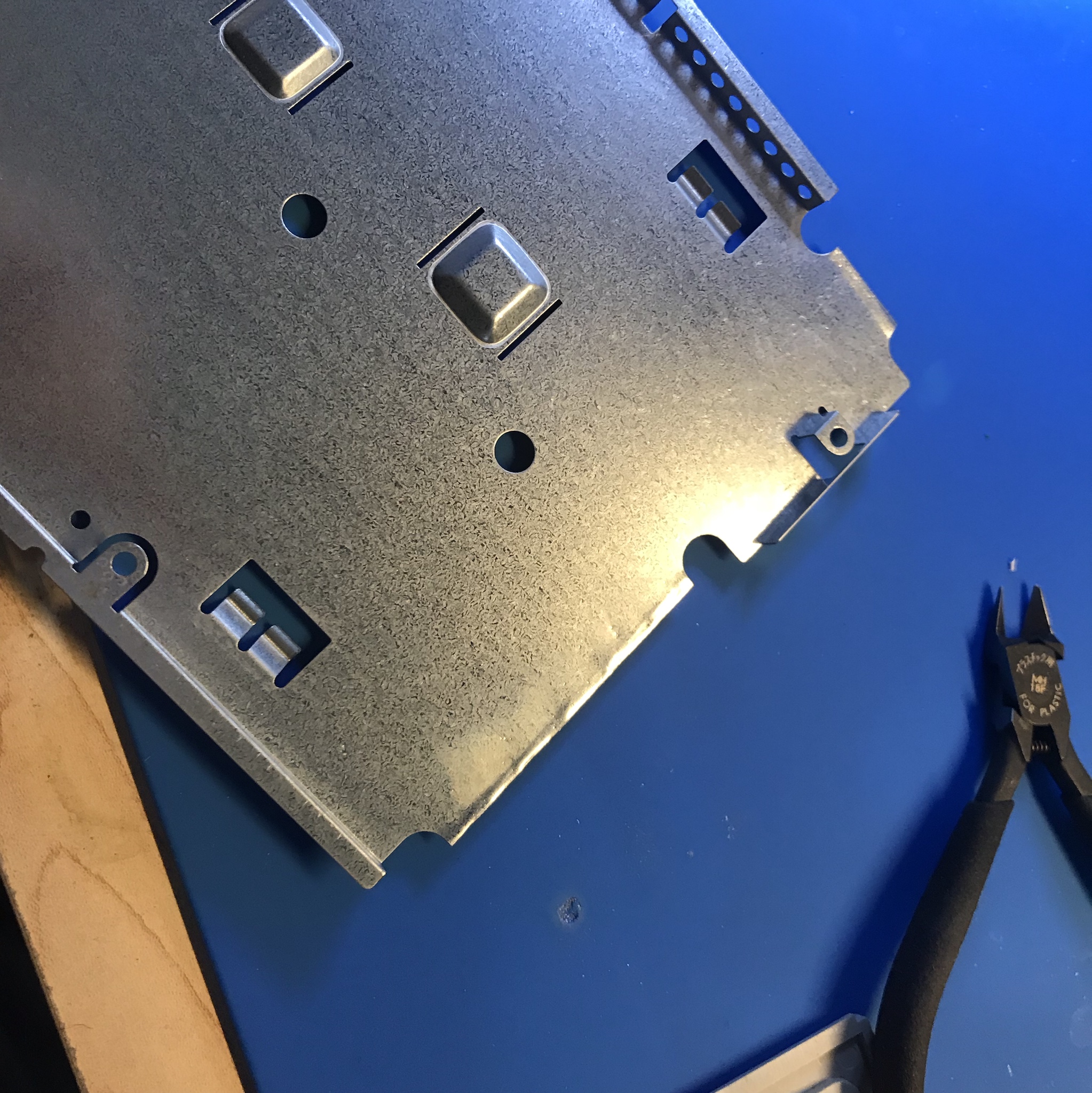
Use side cutters and pliers (bend the metal back and forth until it snaps off cleanly) to remove the following areas highlighted in yellow.
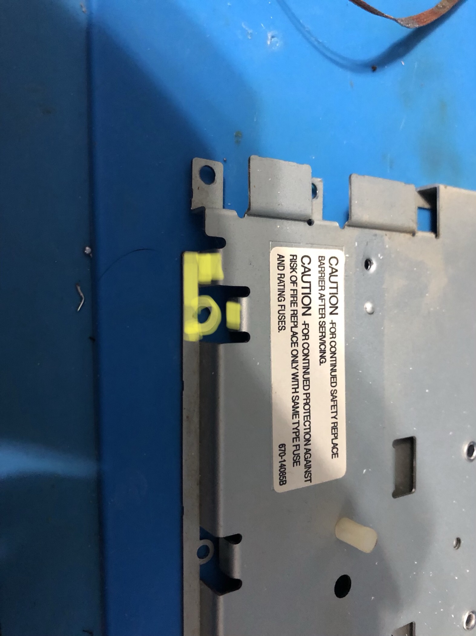

Use side cutters and remove the material highlighted in yellow.
This material is thinner and bends easily. I take pliers or a vice and rock back and forth until the metal breaks cleanly.
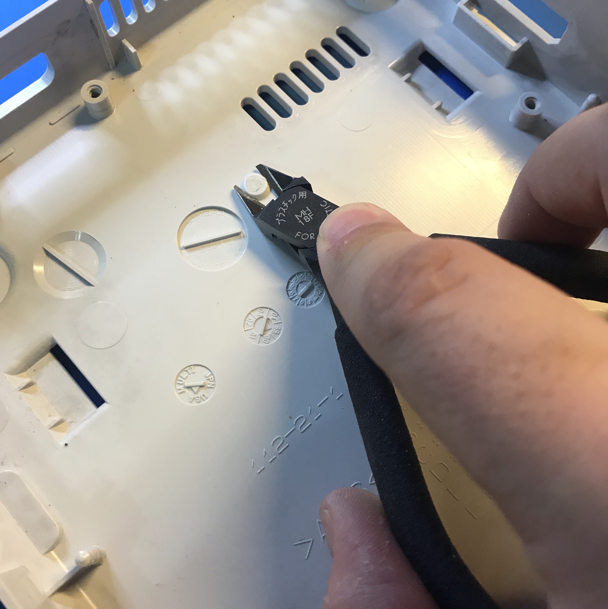
Cut off the plastic screw boss with side cutters.
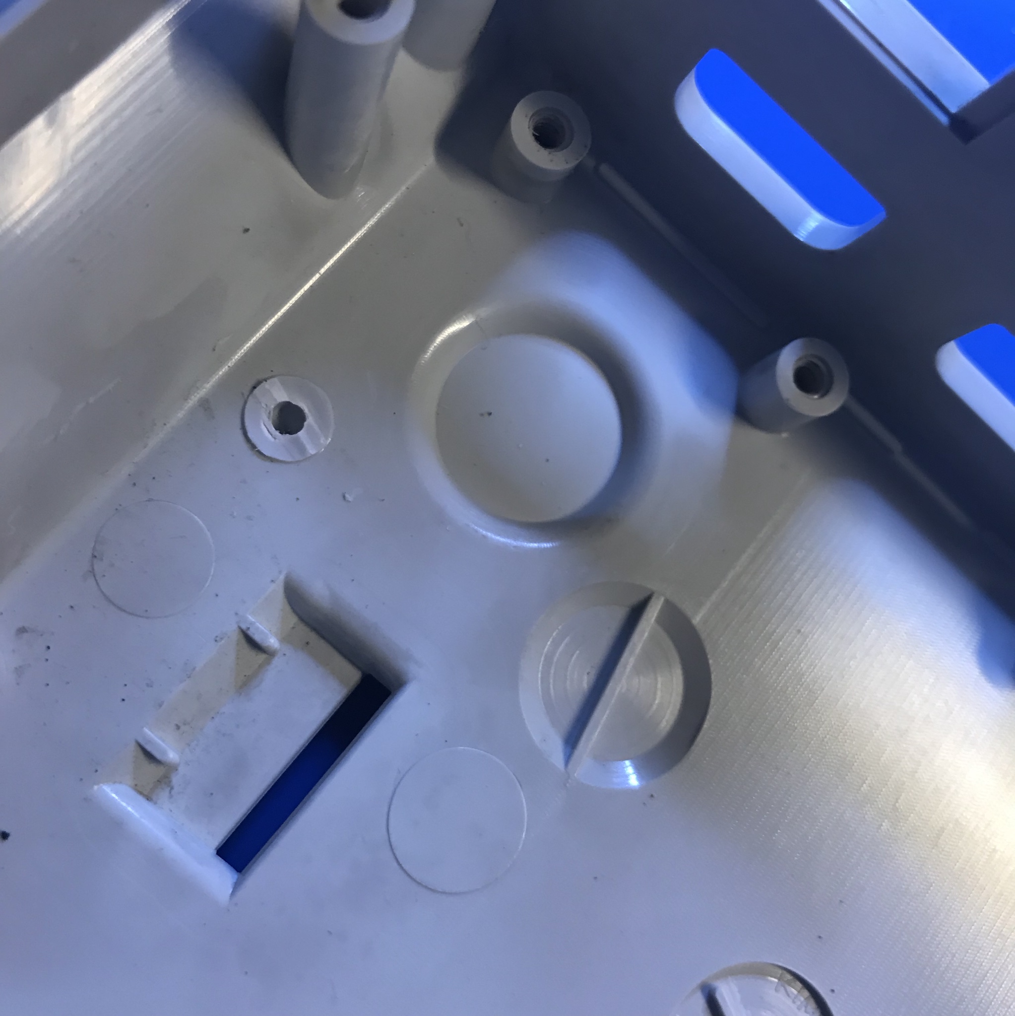
Some consoles have this plastic nub. If yours does remove it with side cutters.
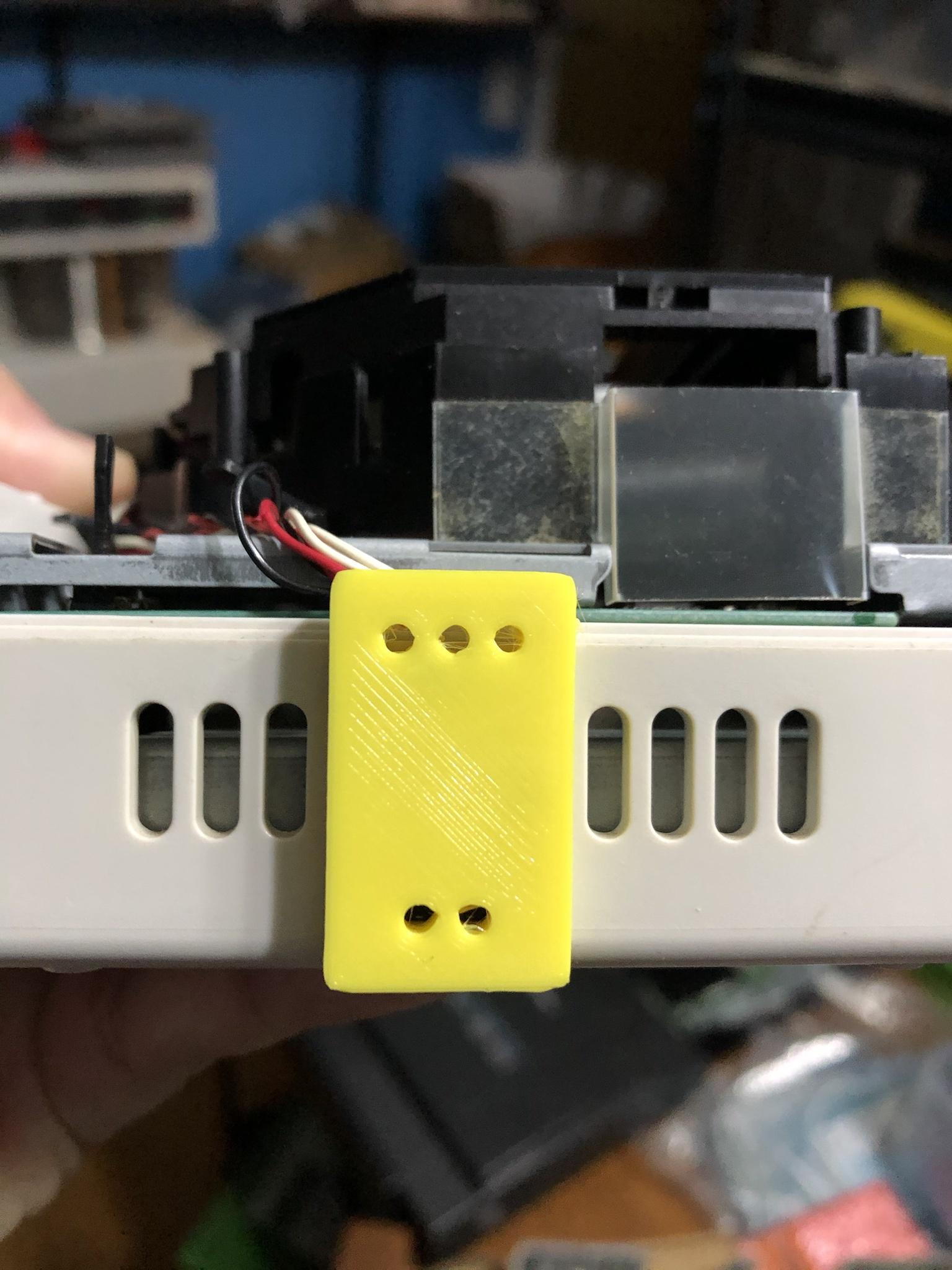
Rev1 Insert 3D Printed connector and drill the 3 holes.
Different cases have different tolerances, the 3D block can be loose or tight. If it’s loose, push it towards the bottom.
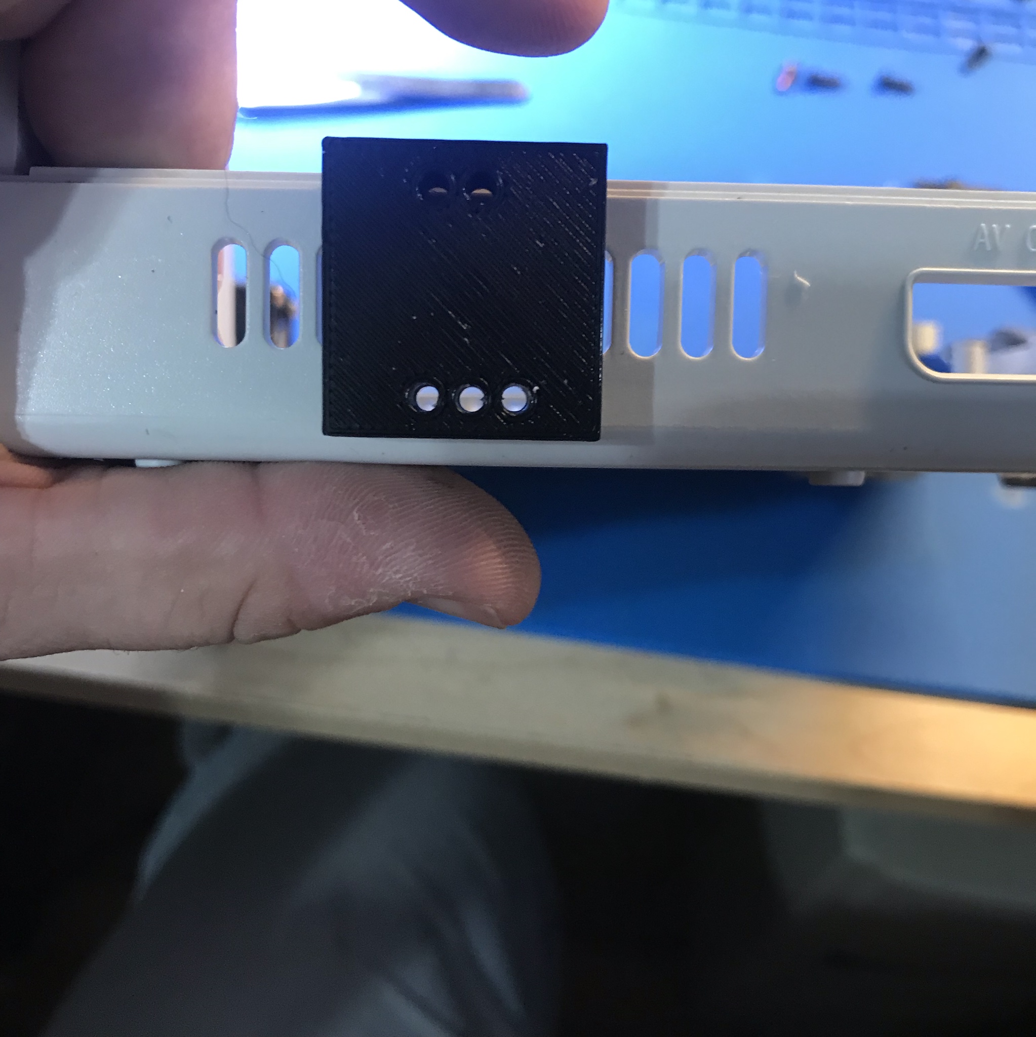
Flip 3D connector and drill the 2 holes.
Different cases have different tolerances, the 3D block can be loose or tight. If it’s loose, push it towards the bottom.
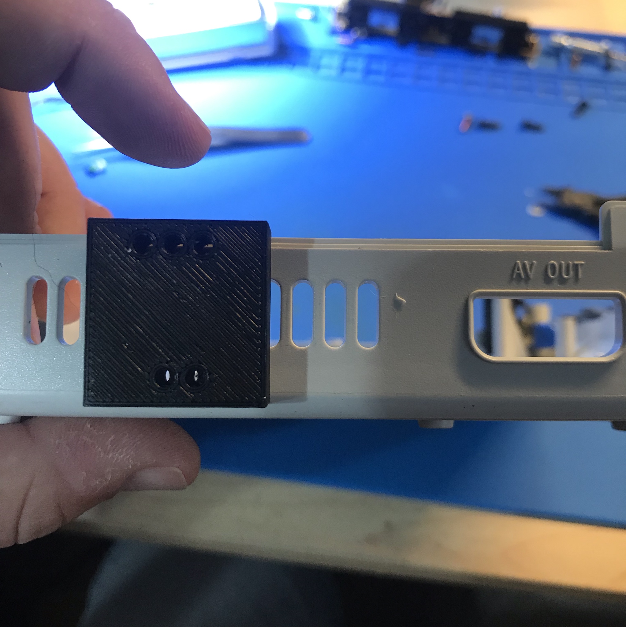
Rev2 Insert 3D Printed connector and drill the 3 holes.
Different cases have different tolerances, the 3D block can be loose or tight. If it’s loose, push it towards the bottom.
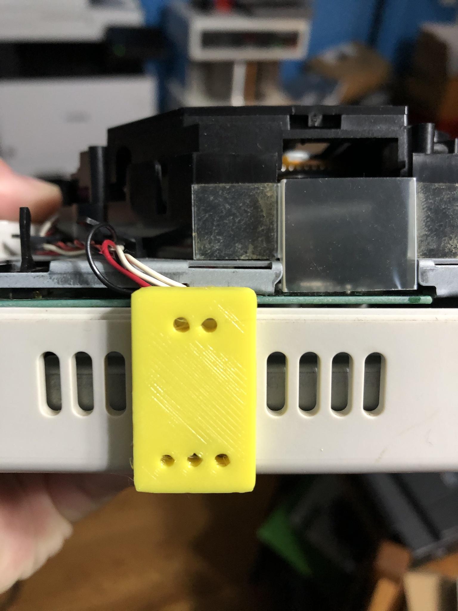
Flip 3D connector and drill the 2 holes.
Different cases have different tolerances, the 3D block can be loose or tight. If it’s loose, push it towards the bottom.
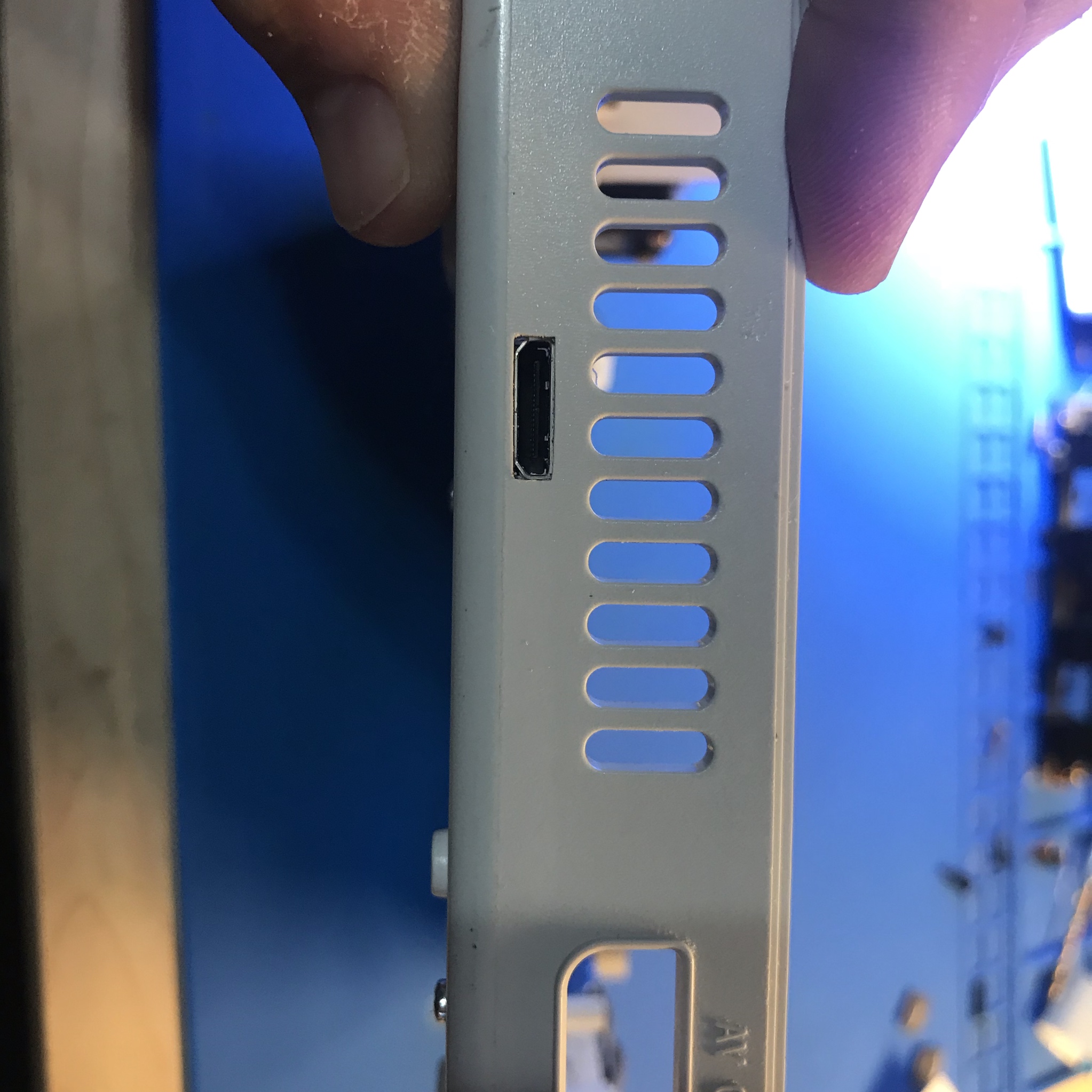
Use the small square and flat files and square the hole up. DO NOT make the hole larger than what the drill bit did. We are just squaring the hole.
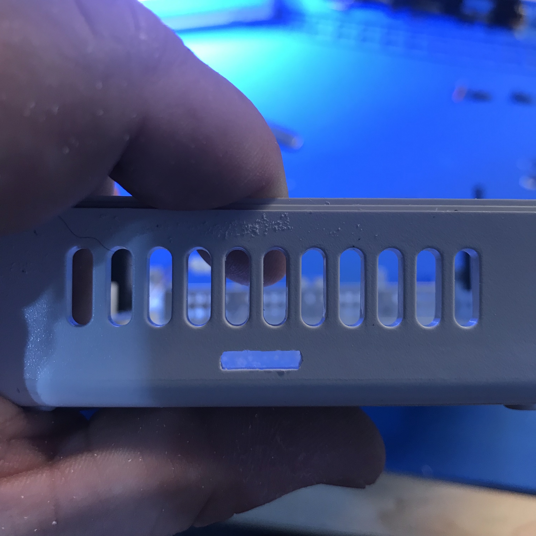
Slowly file only removing a little bit of material. Then check for fit. Make sure the bottom metal shield is in place. Repeat these steps until the board can slide in firmly and lay flat.
Drill two small holes, using the PCB as a guide and mount PCB with supplied M2 screws and nuts.
Tip, drill 1 hole and mount screw. Then drill the other hole and mount screw.
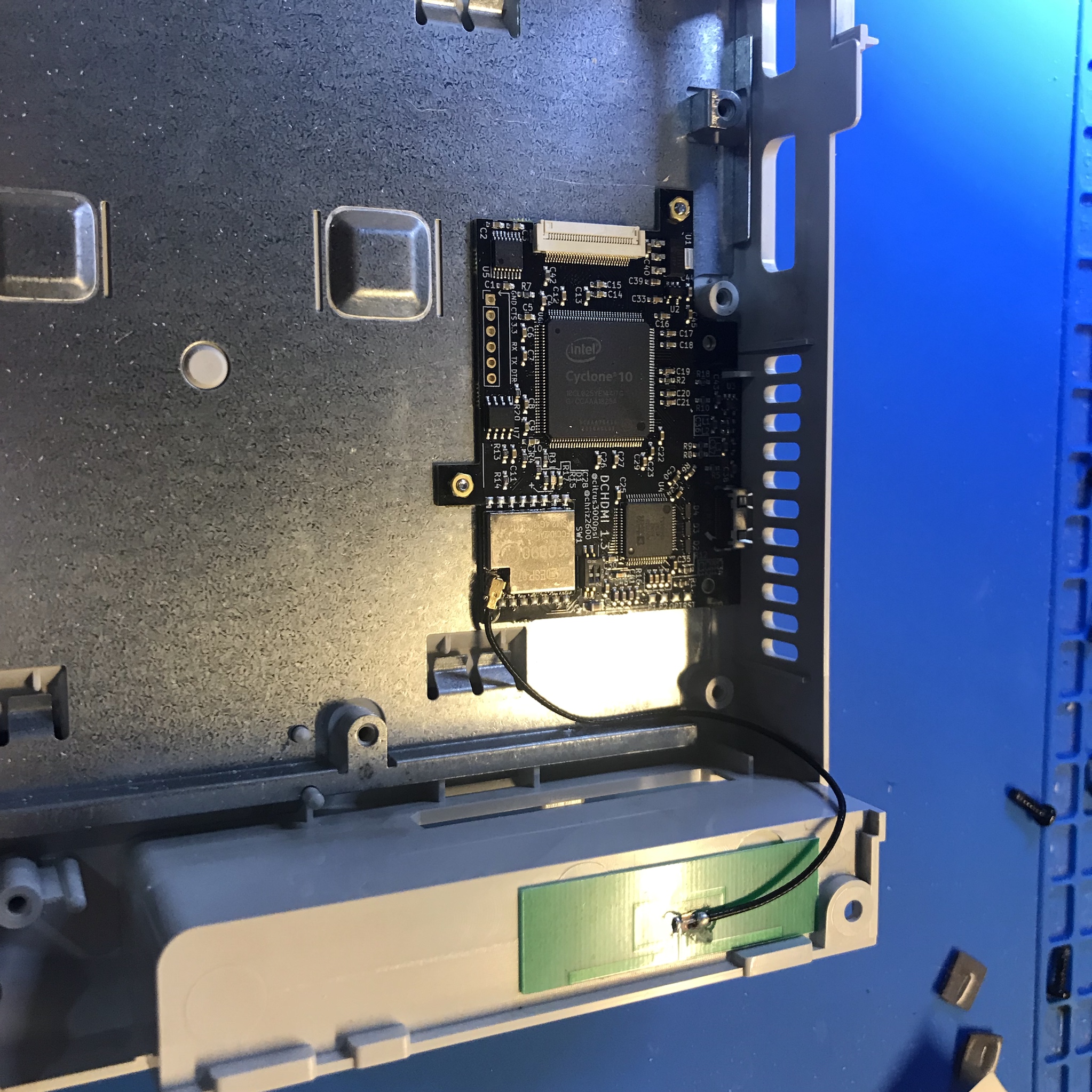
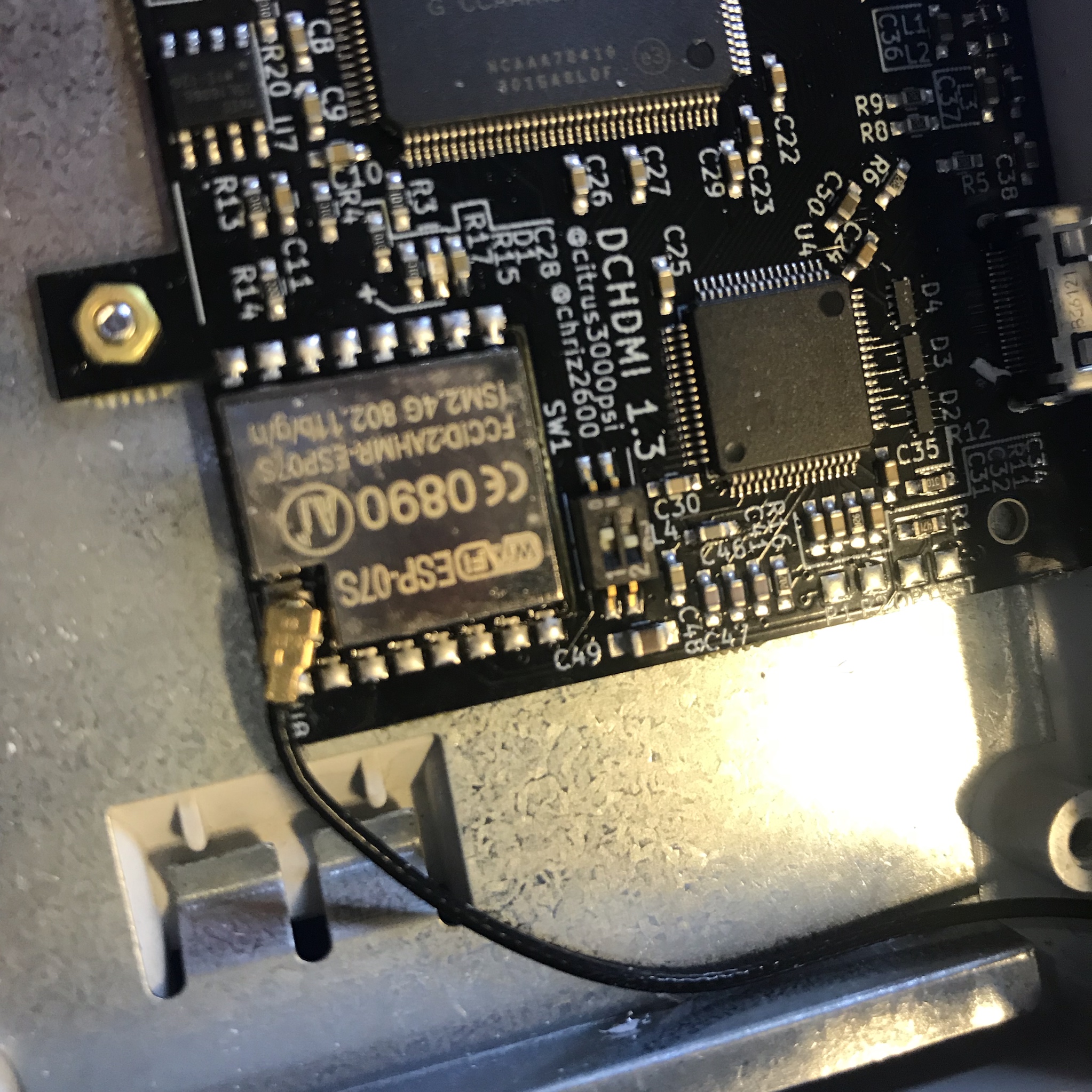
Install the provided Antenna, and route to the edge.
Stock GD-ROM and USB-GDROM should install like this:
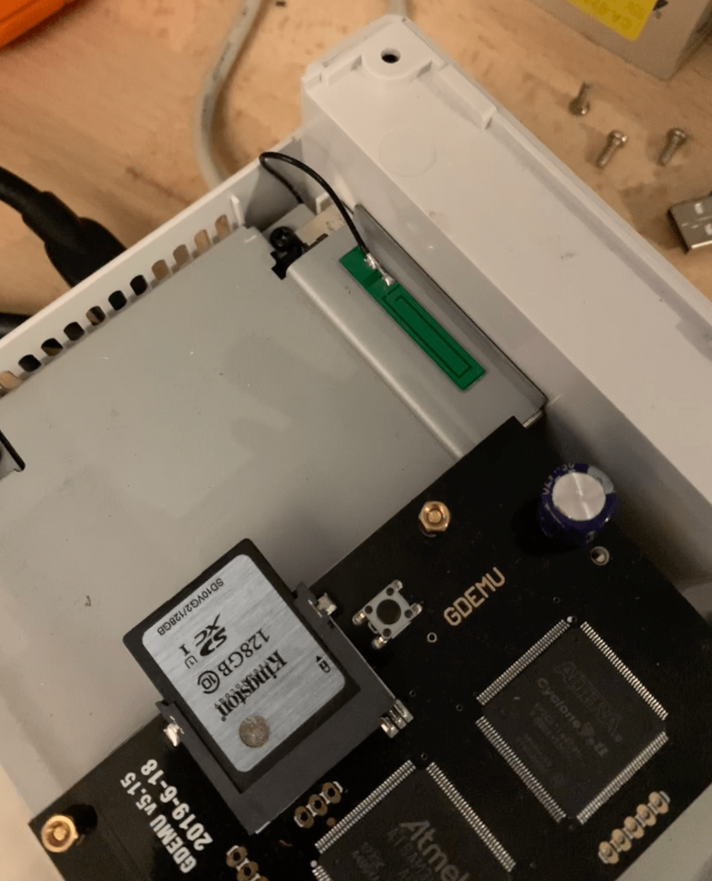
GDEMU users should install like this:
Wait to connect to metal shield until install is finished.
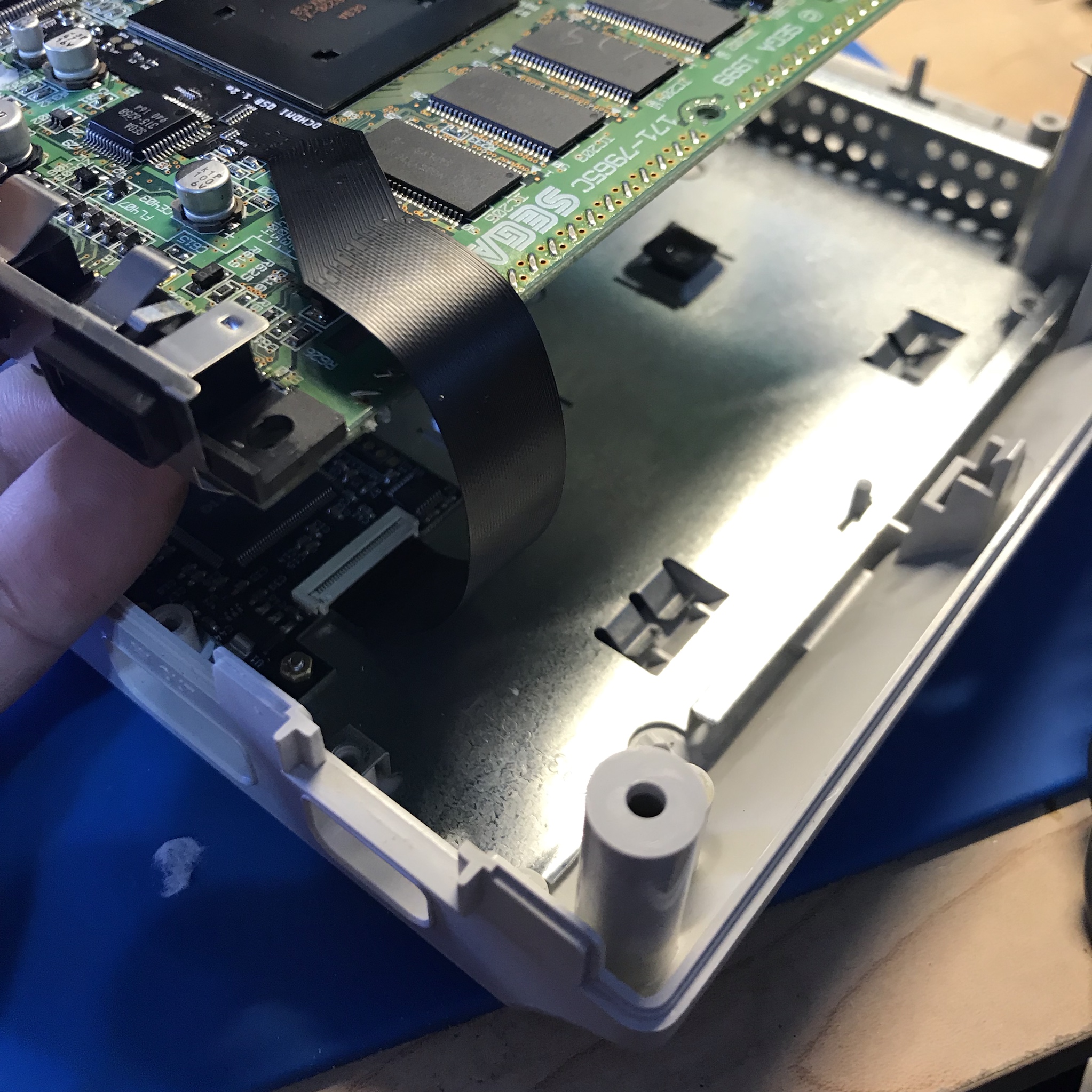
Step 3: Installing the Flat Flex Cable
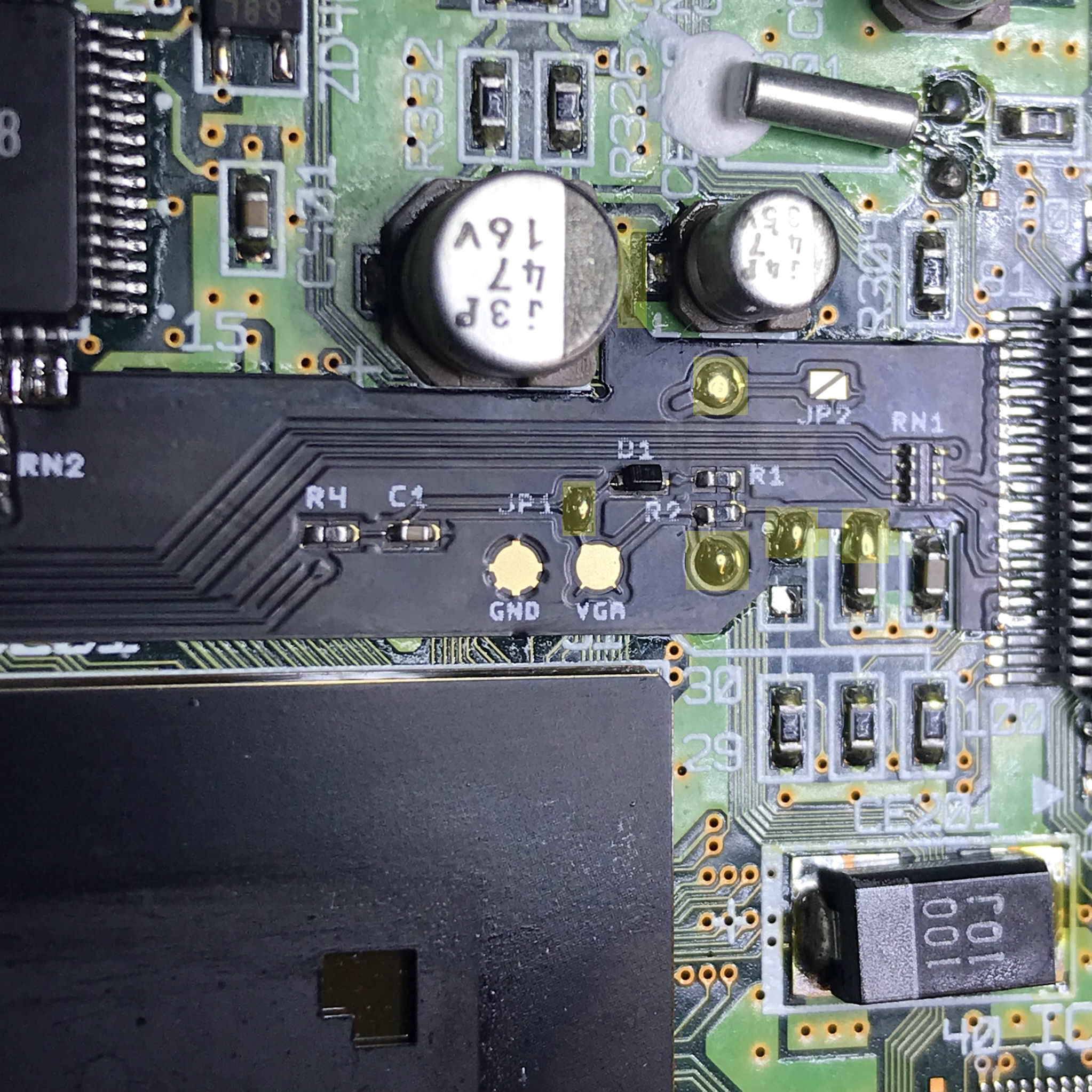
Remove R610 & R609 that are highlighted in yellow. You can discard the resistors.
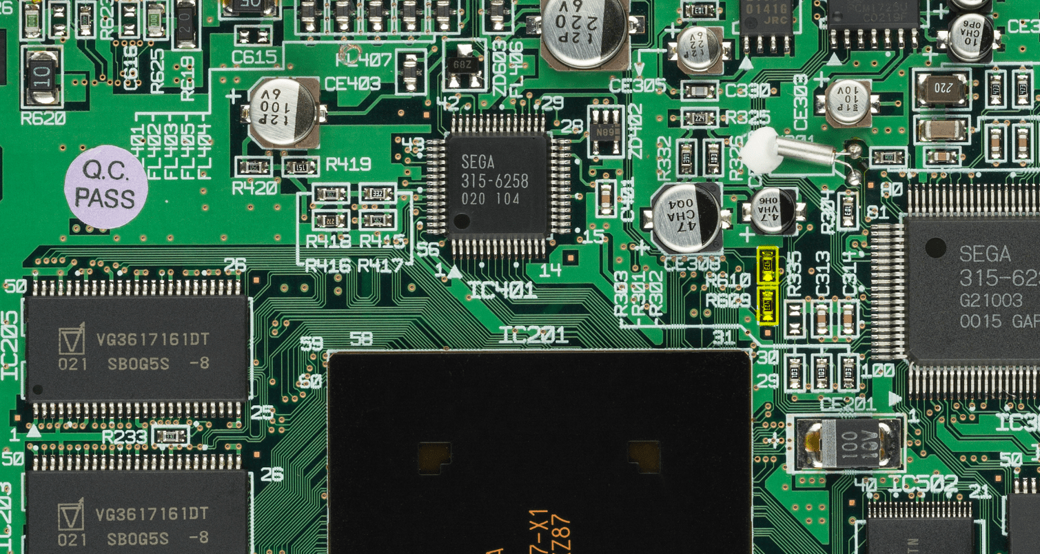
Remove Excess solder from pads R610 & R609 with desolder braid.
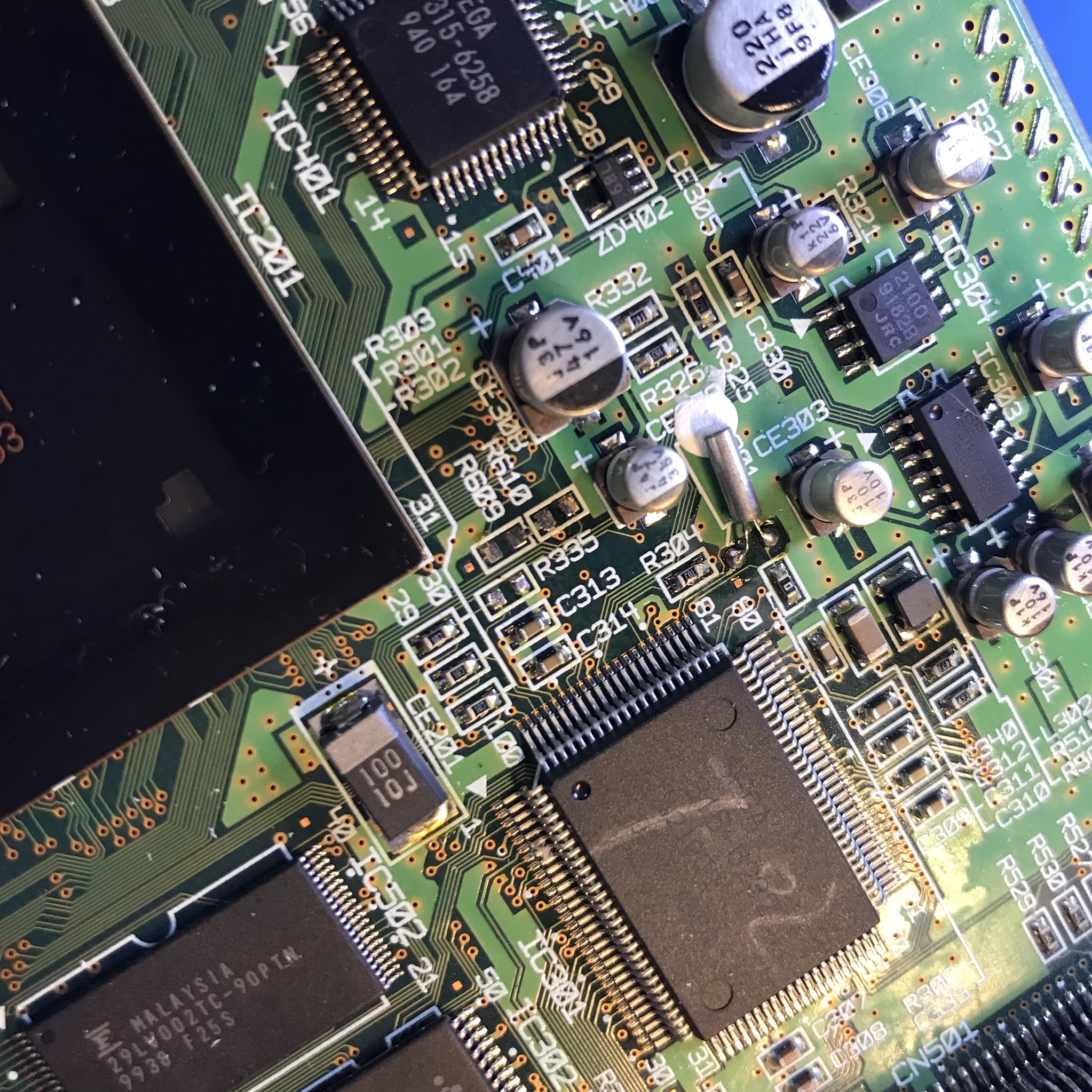
Some motherboards have R335 populated, and some don’t. This is normal, do not remove it.
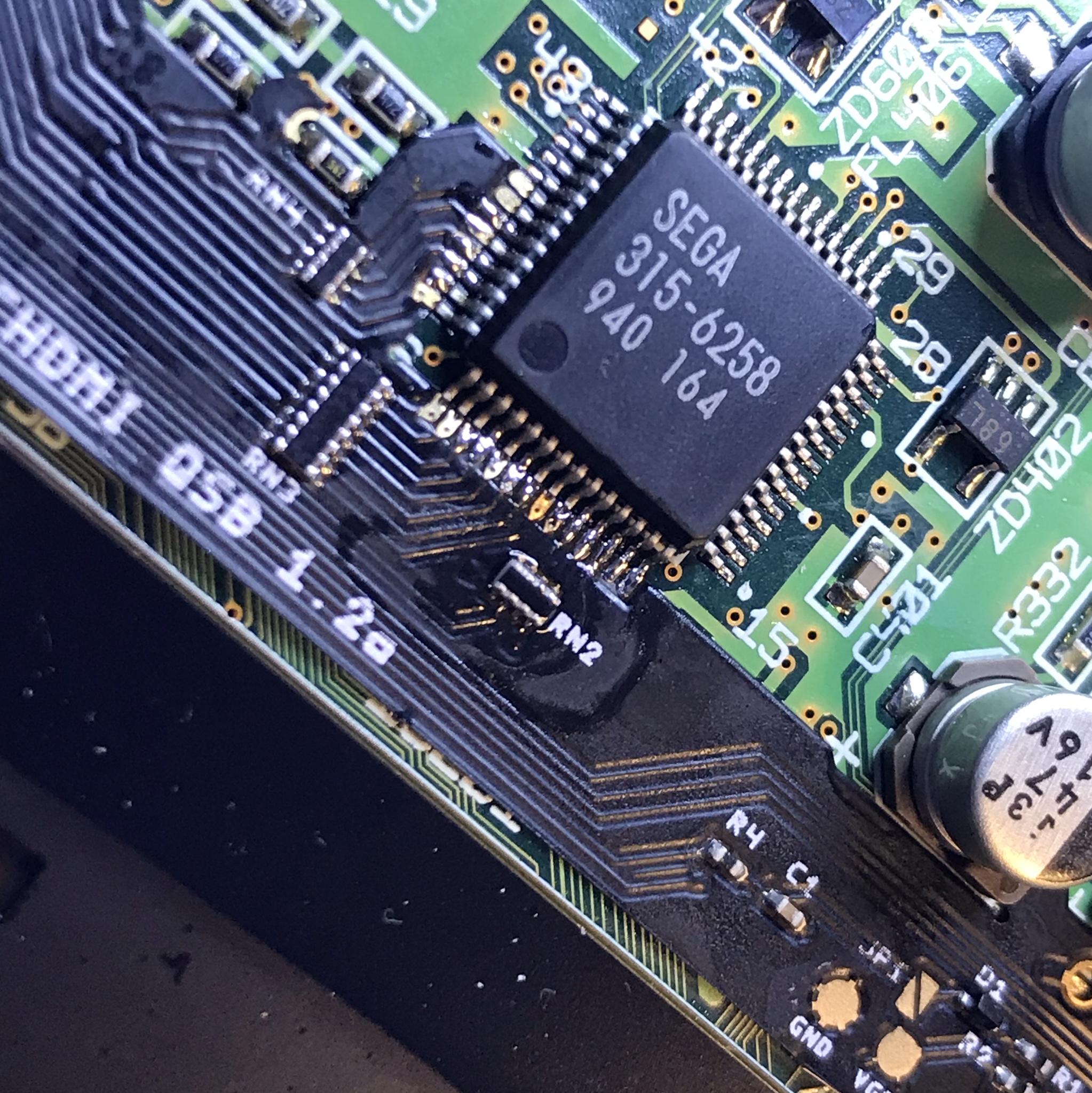
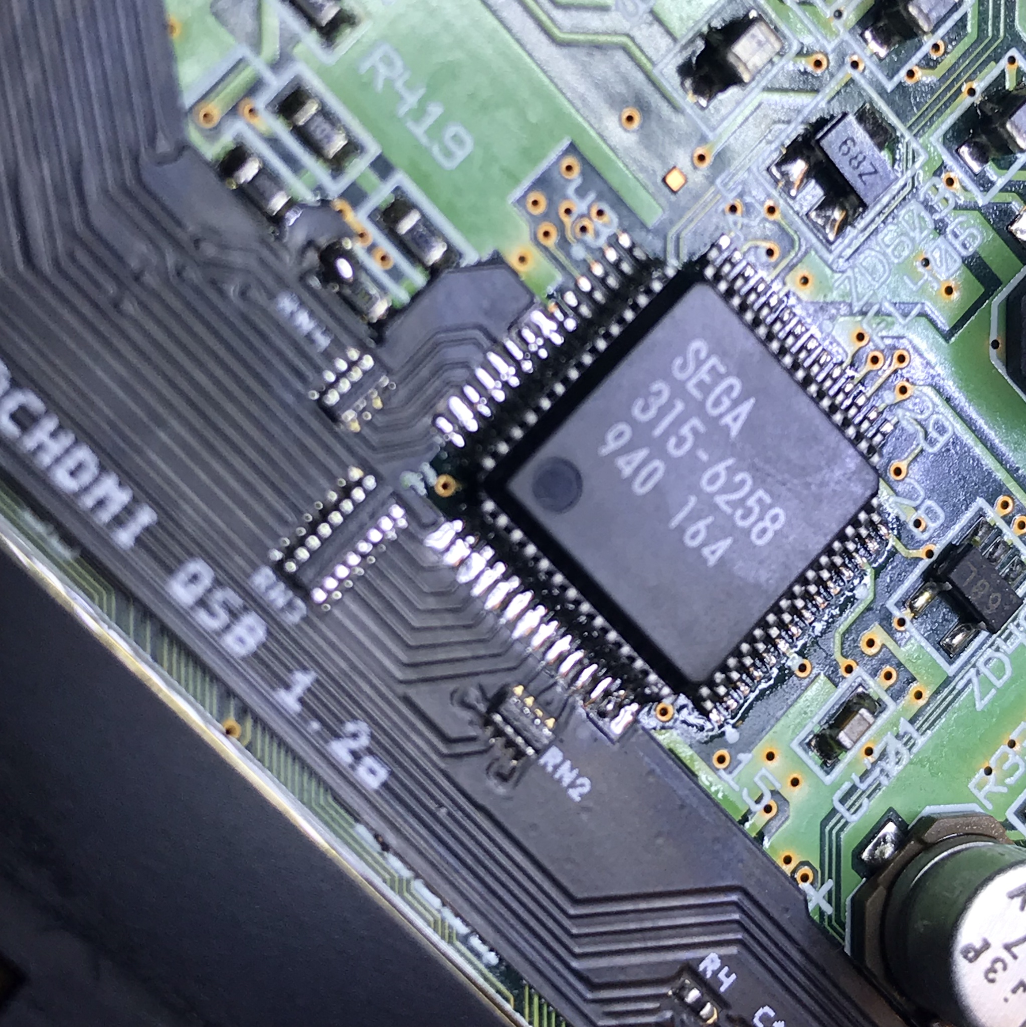
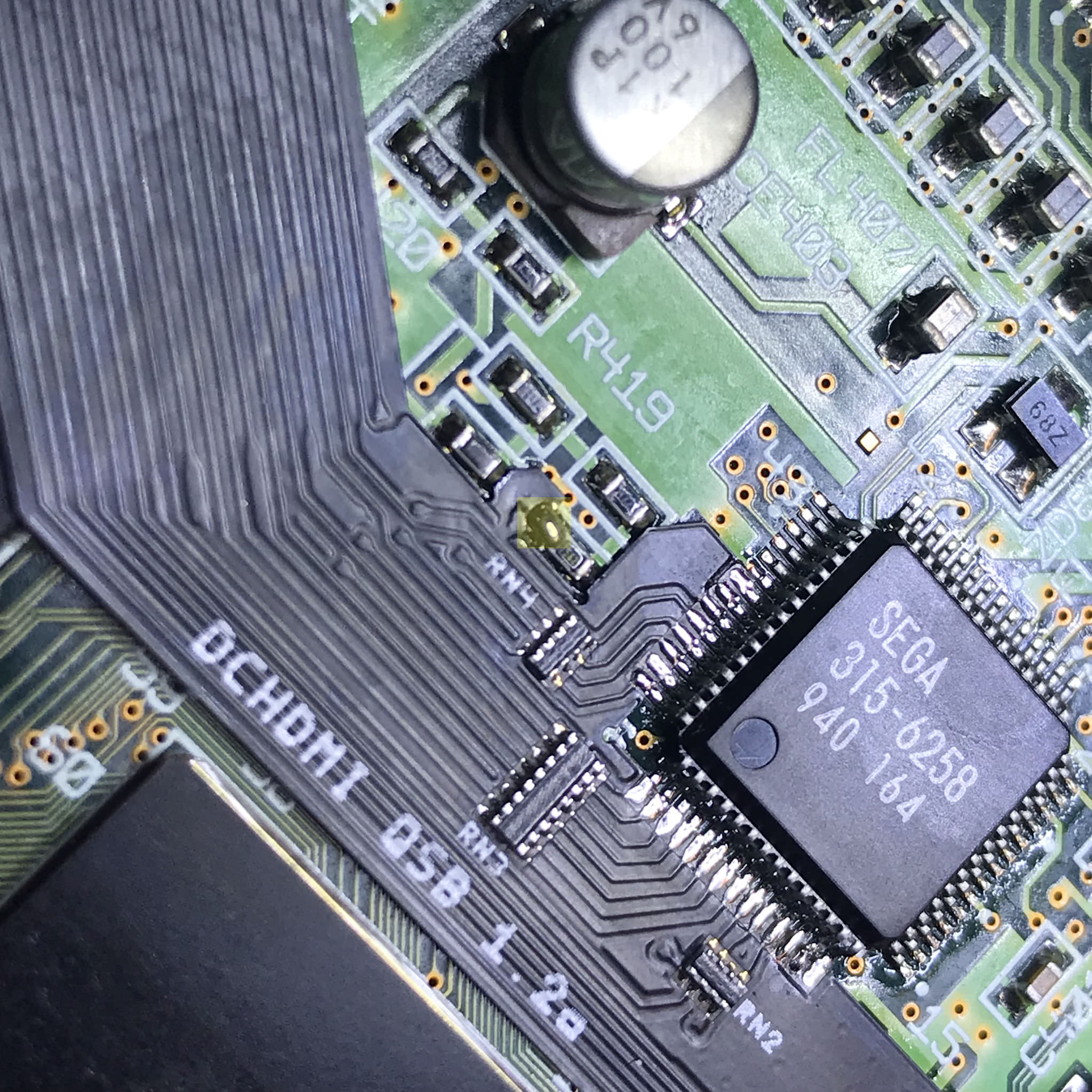
Align Flat flex on with Audio IC and tack into place.
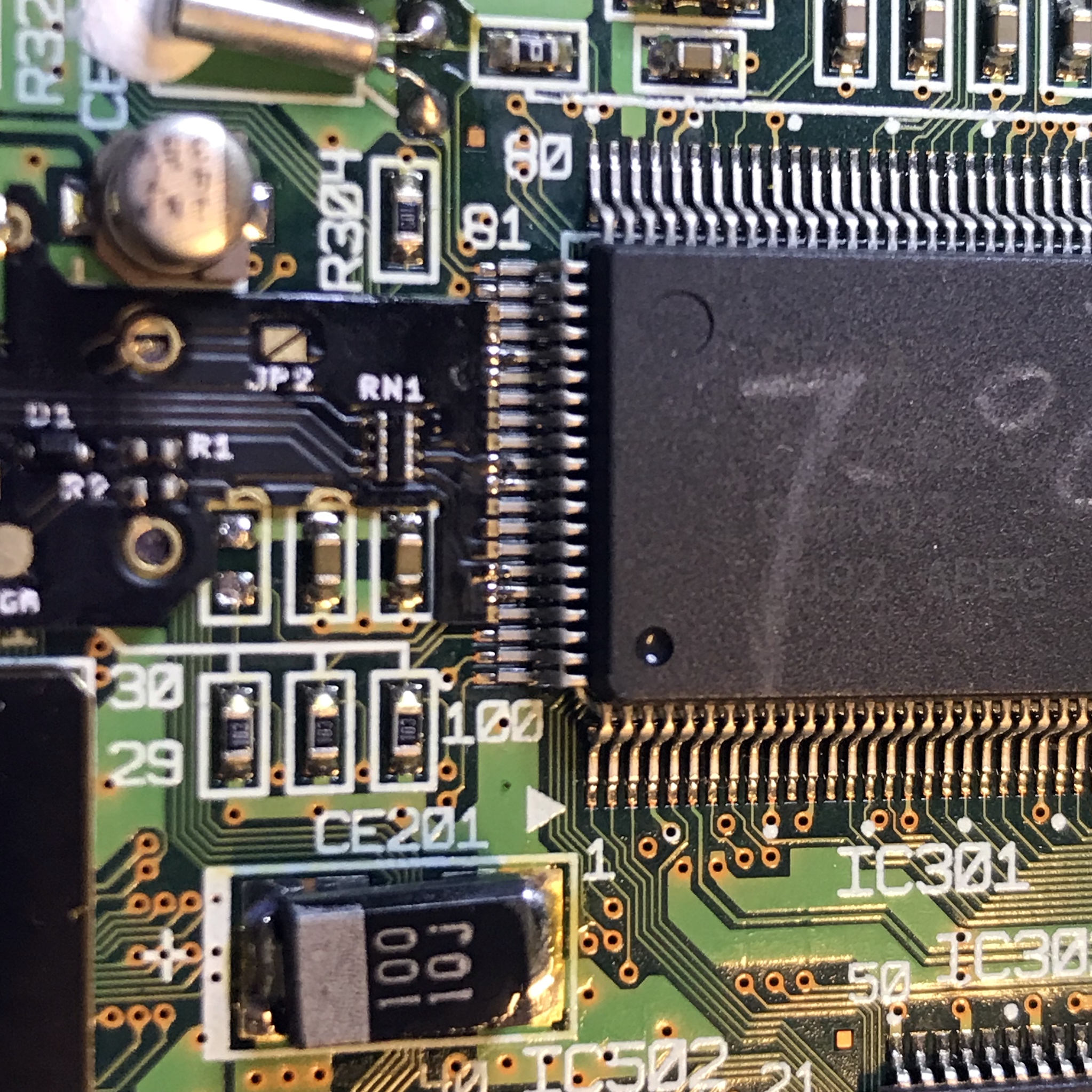
Align Flat flex with the video DAC and tack into place.
Solder the rest of the flat flex into place.
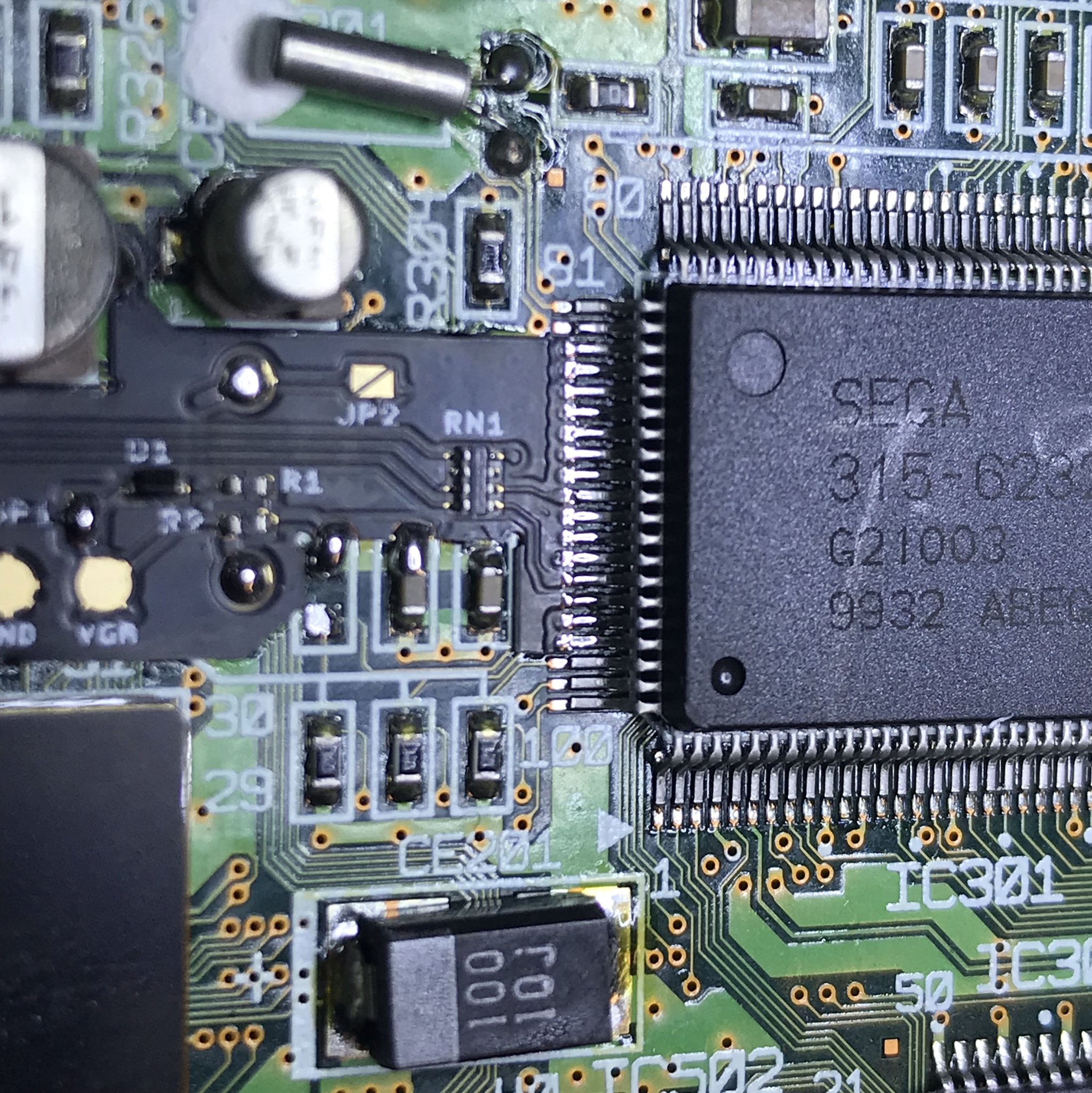
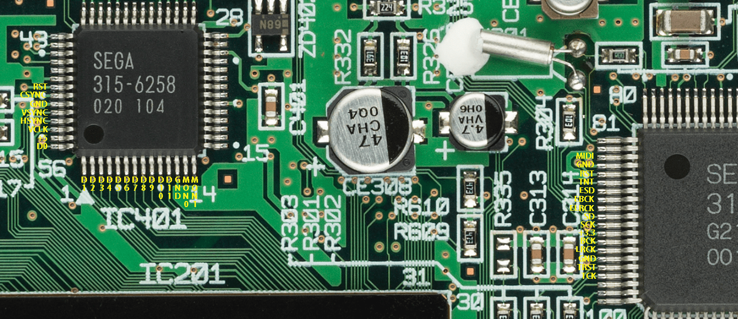
Solder all the areas highlighted in yellow to the flex & motherboard.
Check for shorts with a multimeter, there should be no adjacent pins connected.
Refer to the image below, for a pin map. Not all pins hooked up on flex cable are used.

Step 4: USB-GDROM in game reset prep
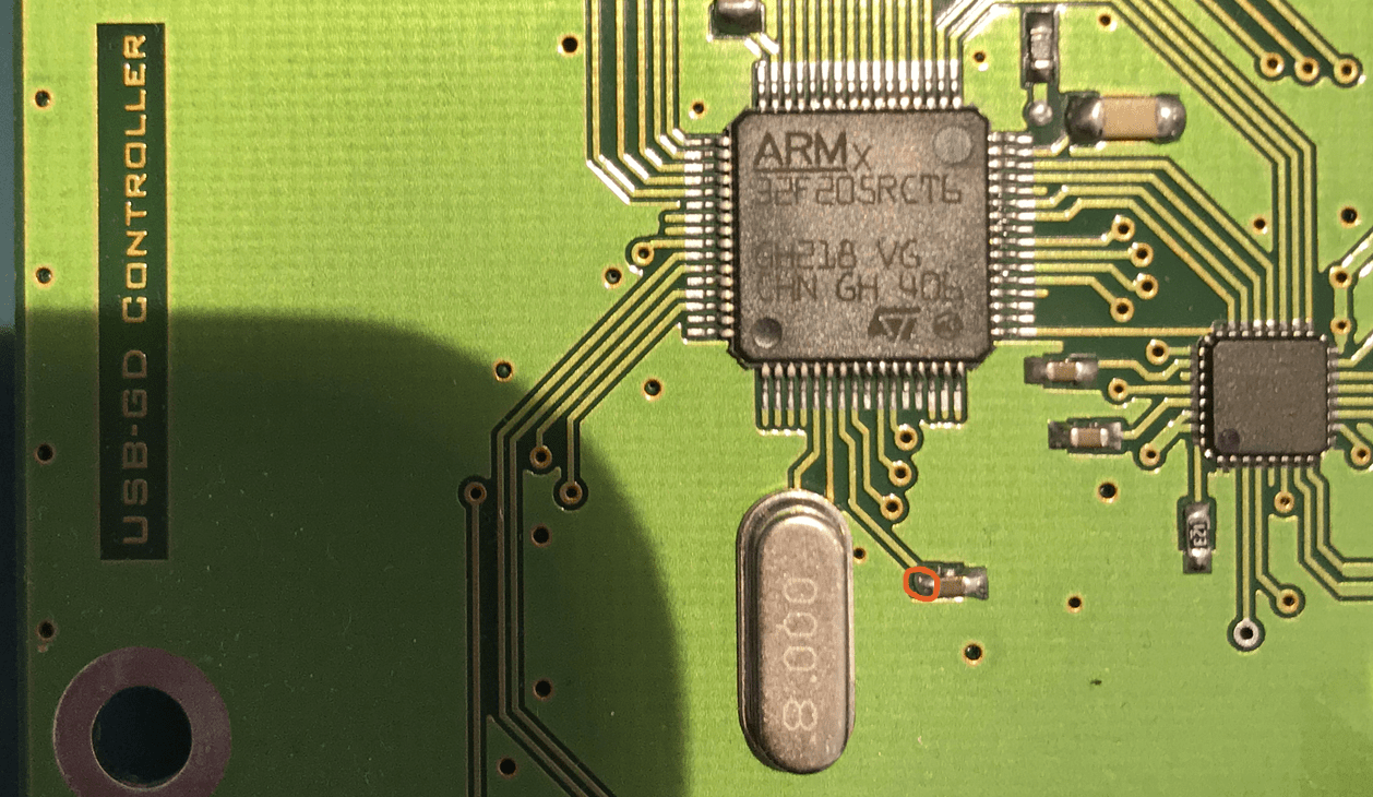
If you have a USB-GDROM and want to use the in-game reset to get back to the menu you must hook up the OPT on the PCB. If you do not care about in-game reset OR do not want to solder a wire to your USB-GDROM please skip this step. By choosing to hook up this wire, you will lose LED functions. The LED is strictly visual.
Solder a long wire (300mm) onto pad OPT on the mainboard. Wire size is not important. It can be as small as 30 AWG.

Flip the bottom switch to ON located on SW1.
Step 4.1: GDEMU button press
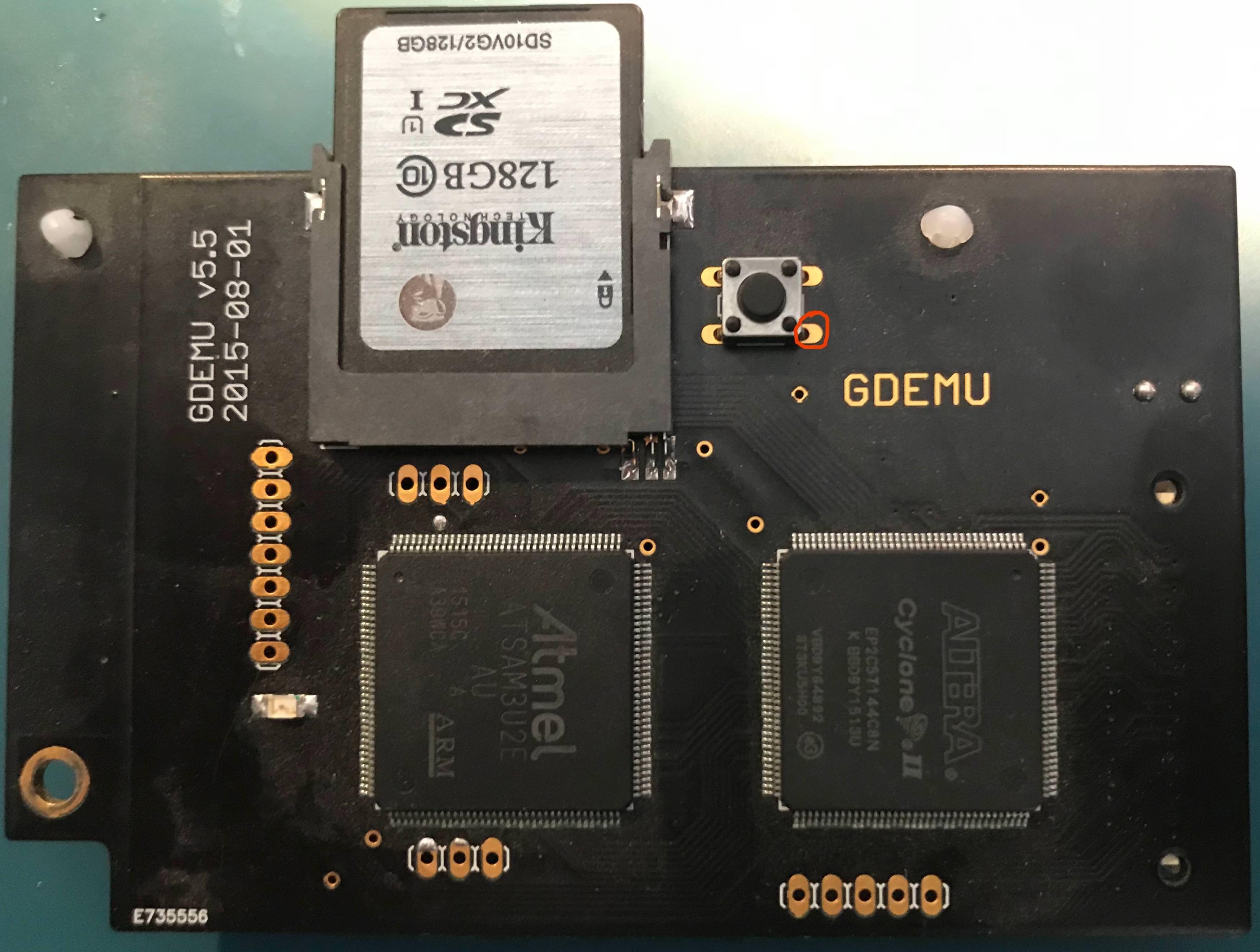
If you have a GDEMU and want to have the DCHDMI control the button press please continue reading (physical button presses will still work). If you do not care about the button press OR do not want to solder a wire to your GDEMU please skip this step. By choosing to hook up this wire, you will lose LED functions. The LED is strictly visual.
Solder a long wire (300mm) on to pad OPT on the mainboard. Wire size is not important. It can be as small as 30 AWG.
Flip the bottom switch to ON located on SW1.

Step 5: Gamepad & Reset Wires
Locate R601 & R602 and solder two long wires.
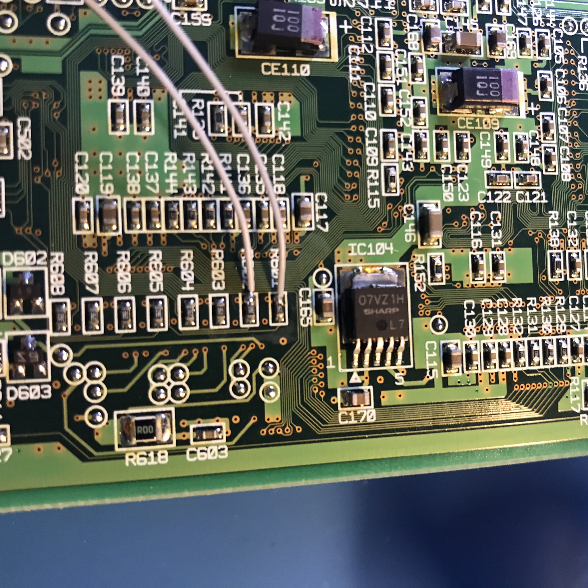
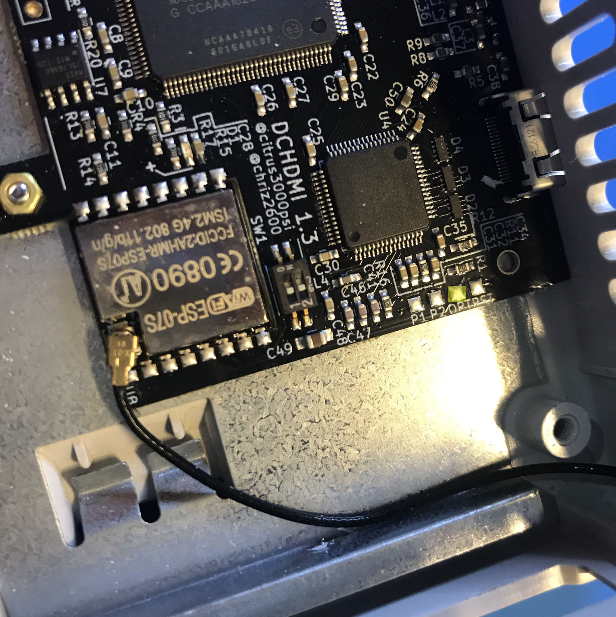
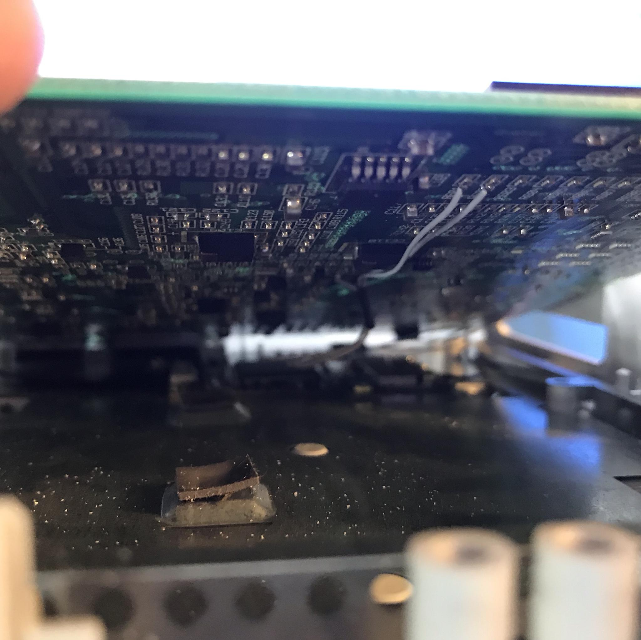
Locate the test point in the image and solder a long wire.
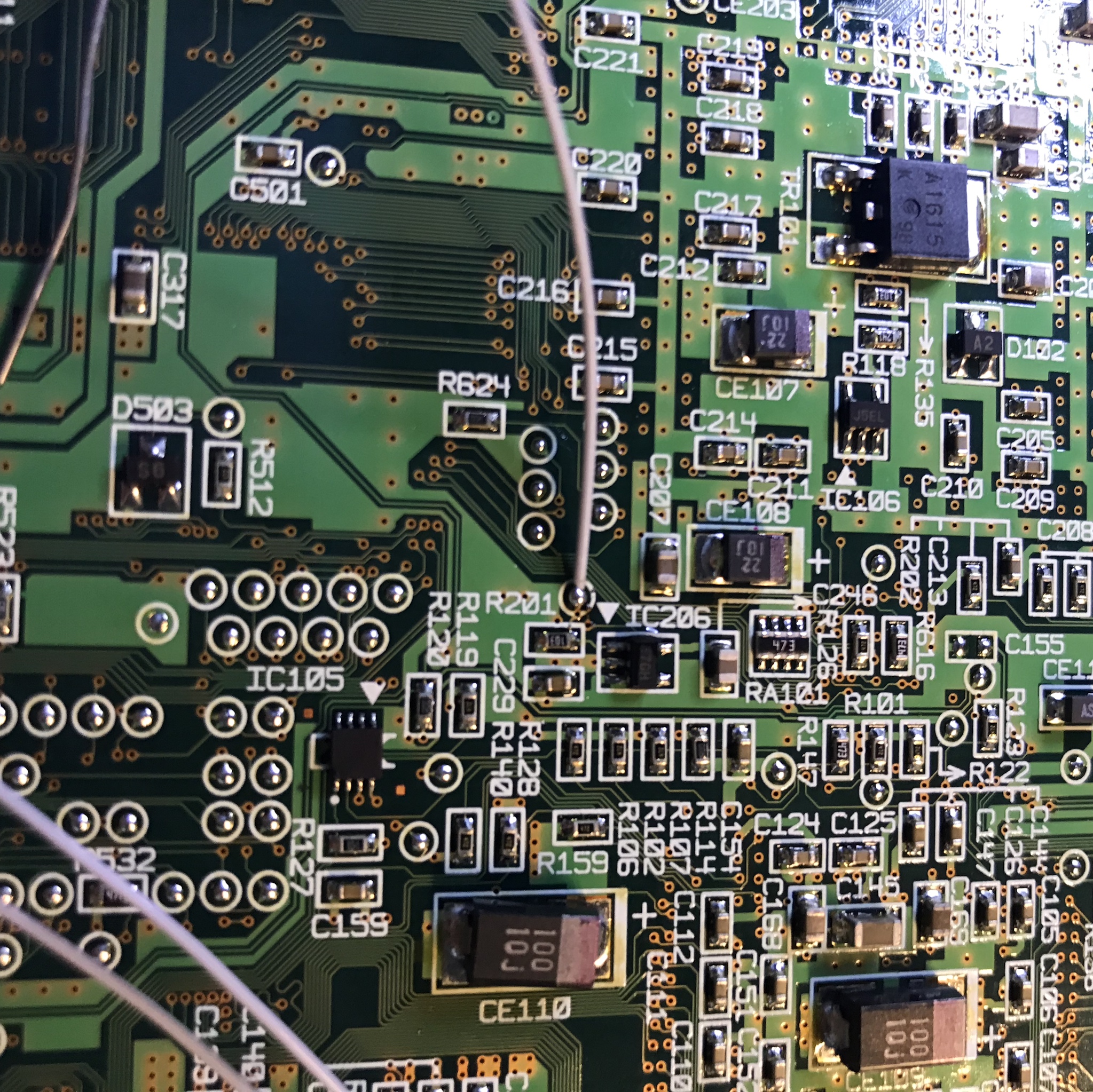
Solder wire from R601 to P1, solder wire from R602 to P2 and solder wire from the test point to RST. I solder the wires with the motherboard in this position to help keep the wires short.
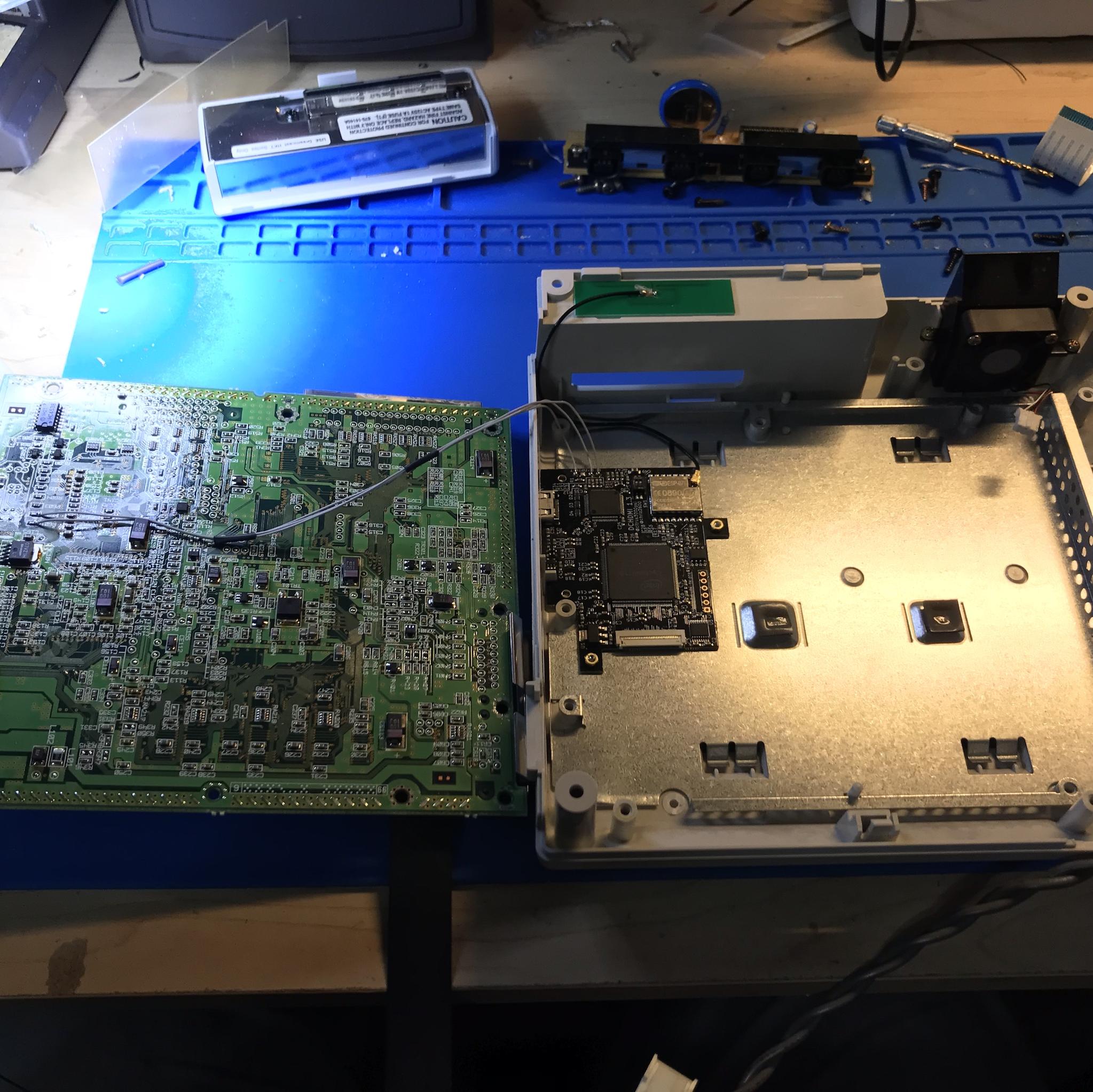
Step 7: Install Main Board
If you have the optional GDEMU or USB-GDROM wire, route this next to the antenna wire.
Install Flex cable to main PCB, this is a flip lock FFC Connector.
With everything hooked up, set the motherboard in place. Verify the Pad & Reset wires are not pinched.
Step 8: Testing HDMI output
Reinstall Top Heatshield (MAKE SURE FLEX CABLE IS NOT PINCHED), Power supply, Gamepad port (Don’t forget to plug in the fan cable), GDROM (DO NOT INSTALL OPTIONAL USB-GDROM OR GDEMU WIRE YET).
You should have HDMI video, if not make sure the FFC cable is seated properly.
Pull up the OSD to make sure you install the pad wires correctly (Left Trigger + Right Trigger + X + A + Start)
With the Dreamcast on the dashboard (it must be the dashboard, i.e., if you have the USB-GDROM menu up, you will get false readings) pull open Test/Info section of OSD. You should see all hearts. If there are any X referring to this image and fix the issues:
Once inside the menu, try to reset the console. This will verify you have the Reset wire installed correctly.
After all verifications are complete continue to Step 9.
Step 9: USB-GDROM & GDEMU Wire hookup & Setup
If you are hooking up the optional wire follow these steps, otherwise skip to step 10.
Turn the console on and login into the terminal (See “Advanced Connection to the ESP” in the settings page). Change the “Option wire” from LED to either GDEMU or USB-GDROM.
Make sure the console is off and unplugged (pull power supply).
GDEMU – Solder wire as shown in pictures.
USB-GDROM – Solder wire as shown in pictures.
Reinstall power supply and ODE. Verify the reset or button works from the OSD.
Step 10: Final Assembly
Finish assembly of unit. Make sure all screws are in place.
Install top case.
Congratulations you are done!
Step 11: Final Notes
GDEMU and USB-GDROM (when not in metal shields) emit a large amount of EMI which will break down the wifi signal. The EMI is much worse when the modem is connected to the console (the Modem shares the G1 bus). It is HIGHLY recommended that you unplug the modem before performing an update. This only applies to GD-EMU users and USB-GDROM drives that are not in the OEM metal shield.
Step 12: Troubleshooting No Video after install
This is an important PSA, firmware versions 2.3.3 and 3.0.3 can have issues on a cold boot up in VGA. This doesn’t happen to all consoles but some. Only around 30 units shipped have this firmware. If you do an installation and do not get a video signal you need to switch the output resolution to 1080p (as the default is VGA). This can easily be accomplished blindly by using the controller. Follow this video for how to accomplish this.
Once you have a video signal, insert your wifi information and update. There could be other issues with your install, so if you still do not have video signal after running this command on the controller, continue to the troubleshooting.
- This is the most common issue after an install. My first advice is to slow down and take your time. Many people have damaged units trying to fix their install by reflowing the flex cable 5+ times. Tackle this no video issue in logical steps.
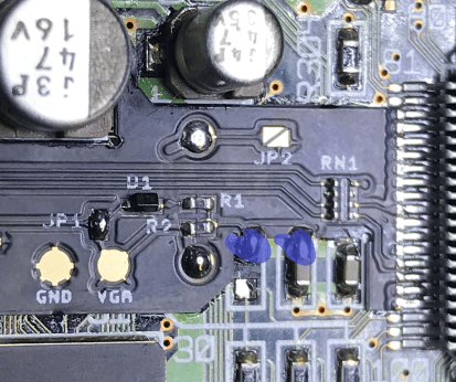
- Verify the DCHDMI is generating an access point. This means the DCHDMI is booting up. If no access point is present verify that the antenna is connected and the points in blue are soldered properly.
- Have you soldered a wire to the GDEMU or USB-GDROM? It says in the instructions NOT to do this until you change the Option Wire from LED in the settings.
- Make sure the GDROM/USB-GDROM/GDEMU is fully seated, if not the DC will not output a signal.
- Plug in a composite cable into the DC analogue port. Confirm you have a composite signal. If you do not have a composite video signal check these pins for bridges on adjacent pins with a multimeter.

- If you have a composite video signal you might be experiencing a firmware bug that was found in Firmware 2.3.2 and earlier (this issue is very sporadic). With the console off hold down on the d-pad with a controller plugged in port 1. Turn on the console while holding down. You will now see a video signal if the issue is related to this bug.