Last Updated: 5th March 2021
PSIO Switch Board Information
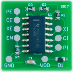
Table of Contents
What is the Switch Board and why do I need it?
The Switch Board actually switches the required data lines and forwards them through to the PSIO cartridge. It does exactly as stated, which is that it is just a switch. In no way shape or form is this a modchip. It does not bypass the system protection or allow booting of copied discs. It is completely invisible to the system, and it causes no harm or effects to the hardware.
Why exactly is it required?
The two signals that are routed out to the expansion port are the CS/ and INT/ lines from the CD controller. The job of the Switch Board is to basically connect them back to the CD-ROM drive when PSIO is unplugged, or you boot a CD as they are needed by PSIO. When PSIO is active, the internal CD interface chip is disabled, and all the accesses to the CD controller are redirected to the emulated CD controller in PSIO. All the hardware registers are still in the same place. The Switch Board is just a switch that triggers when PSIO is plugged in or not.
How do I identify my model so I know what to download?
When you disassemble your PlayStation, the mainboard will have a code marked “PU-XX” where “XX” is your model number.
You may see examples demonstrating that on the top of the board:

and on the back:
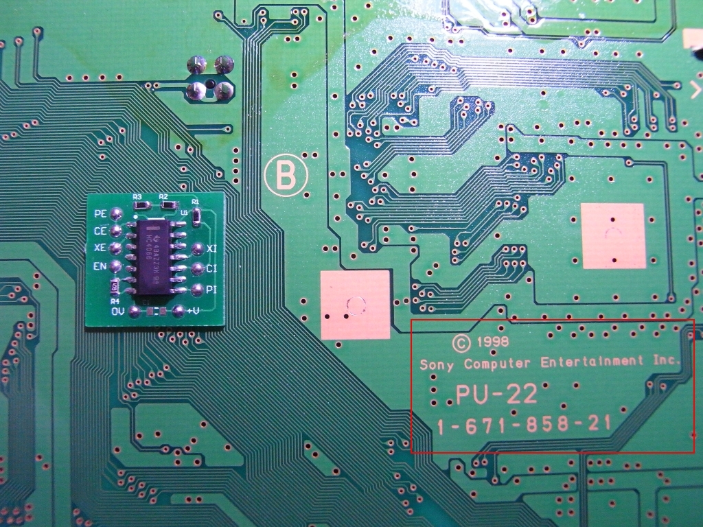
This model number is important to know so you can match it with a “Switch Board Installation Guide” listed on the ‘Downloads’ page.
How hard is it to install the Switch Board?
The soldering required isn’t too difficult, but it is very fine based work.
If you have a soldering iron with a good tip and steady hand, it is possible to do quite easily.
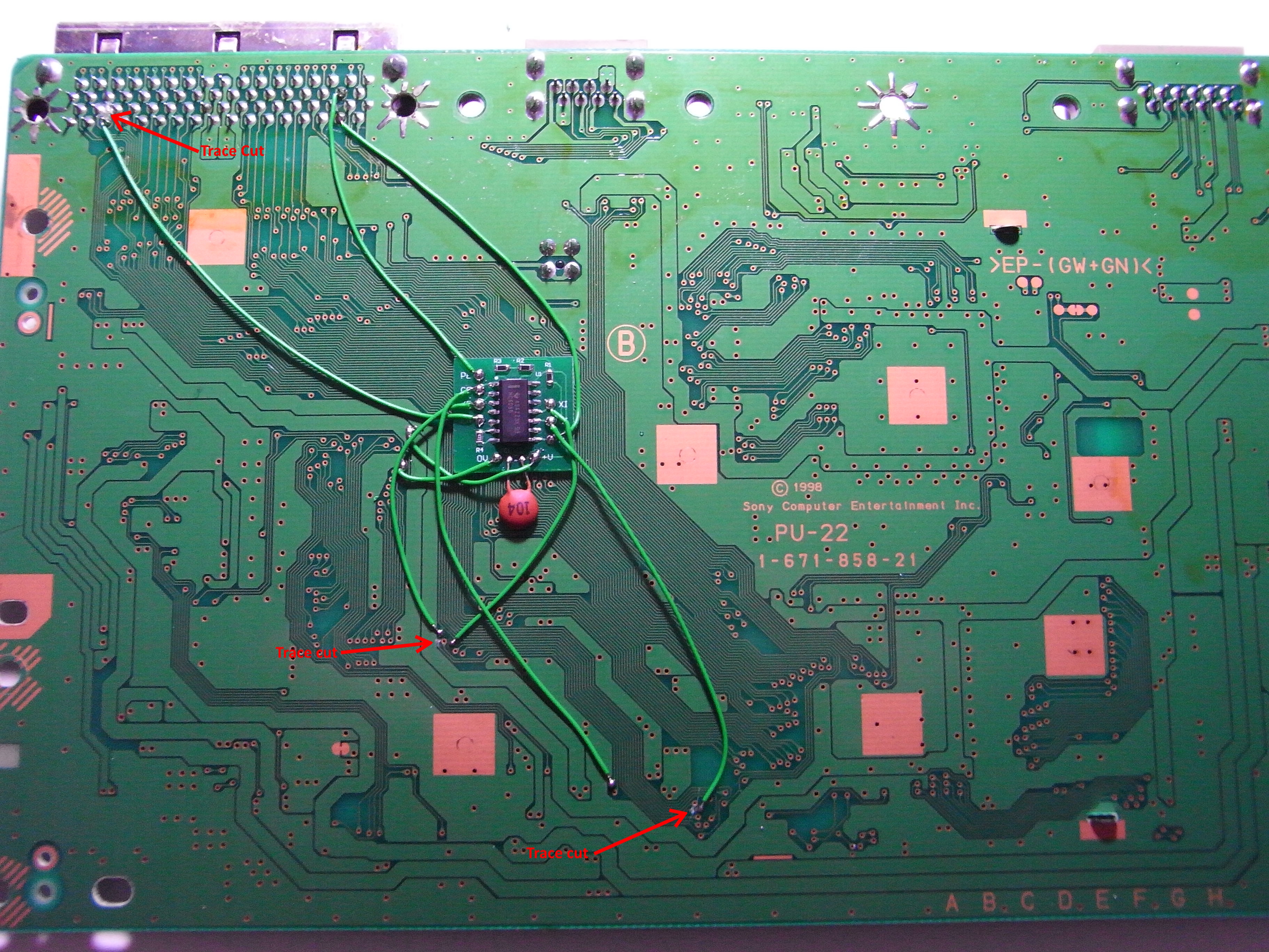
You will be required to cut three (3) traces on the mainboard.
You will also be required to scratch with a knife some vias and then solder to them.
An example of the soldering required:
Can I send you my mainboard so you can do it for me?
Yes. CybDyn have an option to do that in their Store, and more information about it can be read there.
What are the technical specifications of this circuit?
The Switch Board has a maximum input voltage of 3.3V. Do not solder it to a 5.0V rail in the PlayStation. Note that the newer Switch Boards (silk screened as “SB17” on the PCB) now contain a Schottky Diode, which protects against reverse polarity. This was done as a safety precaution since CMOS integrated circuits get extremely hot if the voltage rails are wired backwards. The diode, however, eliminates this risk entirely. Prior to the SB17 revision, we advise that you check that your ground and voltage rails are not backwards before powering on your PlayStation after installing a Switch Board.
Where can the installation documents be found?
In the Manuals section.
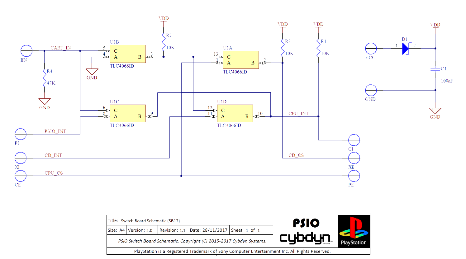
Do you have a schematic of the Switch Board available?
Yes. It may be found in any installation document, but it is also available here: