
Last Updated: 5th March 2021
xStation PU-18 Installation Manual/Diagram
Table of Contents
PU-18 Mainboard Information
- All SCPH-5001
- All SCPH-5501 – 5503
- All SCPH-5552
- (very rarely) SCPH-7001 – 7003
Guide
Installation
- You have to disassemble the Playstation 1 completely to get to the mainboard.
PLEASE REMOVE ALL CABLES FROM THE POWER SUPPLY.
MAKE SURE THAT THE POWER CORD IS DISCONNECTED!
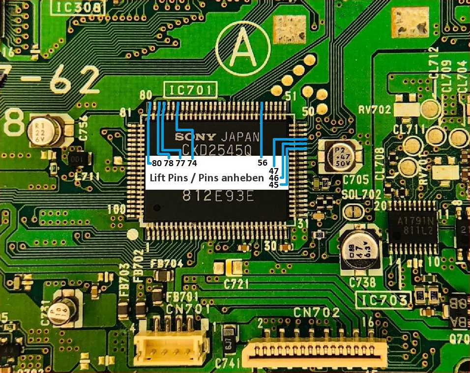
- Search for IC701
IC701 is labeled CXD2545Q. You will find it in the lower right corner.
See picture below

- From IC701 (CXD2545Q) you have to lift the following pins:
45, 46, 47, 56, 74, 77, 78 and 80.
Please make sure that only the shown pins are lifted.
- Please be careful not to damage the mainboard when lifting pins.
Use a needle or x-acto knife and a fine soldering tip to simply touch the pin and apply some heat, then gently lift it from underneath using the needle or blade.
(In the picture I have turned the mainboard to get easier access to the pins
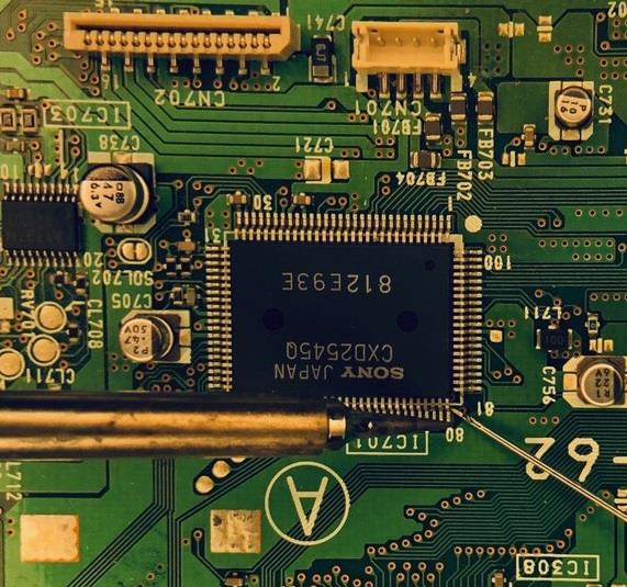
- Please make sure that you have lifted the pins completely. They should have no contact with the motherboard

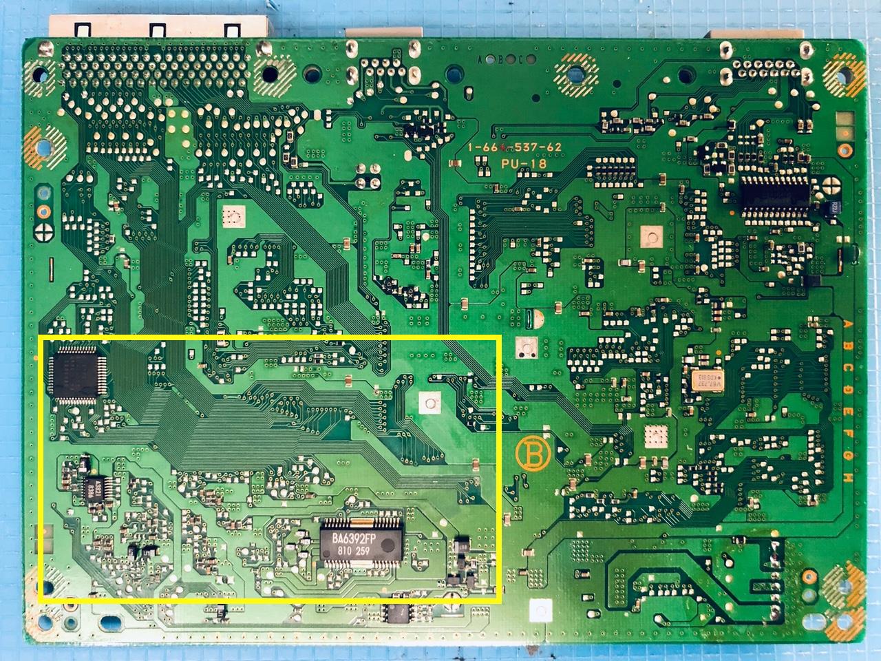
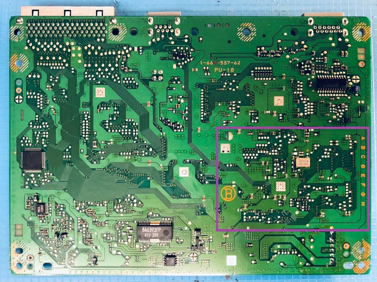
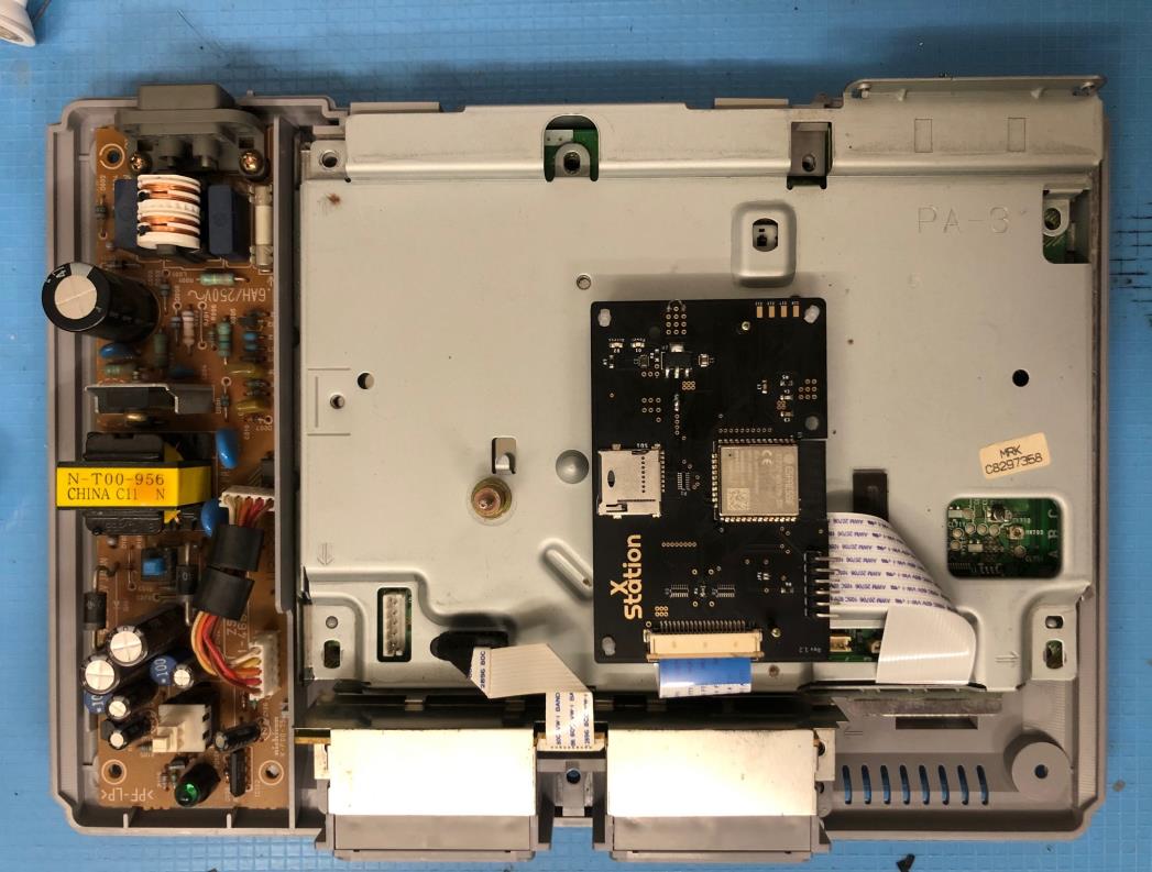
- We are now finished with the top of the mainboard; turn it bottom side up.
Now you have to solder the Quick Solder Board (QSB). Focus on the area marked below.
- The positioning is kept very simple and can already be seen at the solder pads of the QSB.
Simply place the QSB on the mainboard as shown, the yellow markings make it clear again.
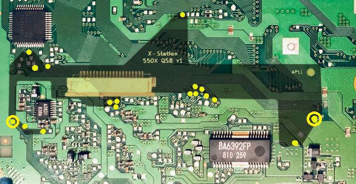
- Before soldering, the via pads on the left and on the right (yellow circle marked in the picture above) need to be lightly scratched.
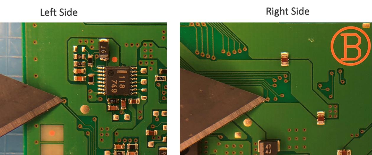
After preparing it should look like this:
- on the left

- on the right

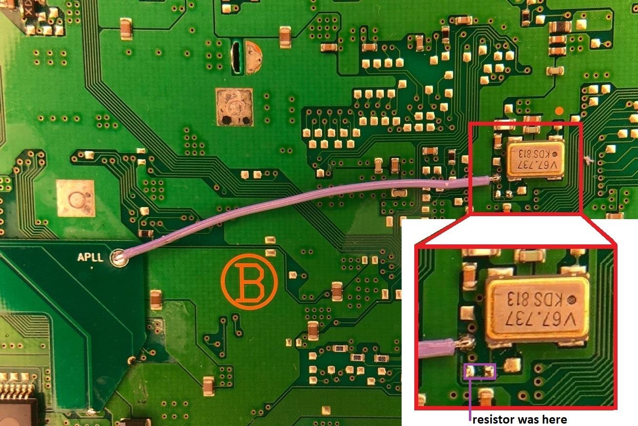
- Now you have to desolder/remove one small resistor, which is located next to the OSC V67.737 KDS813 in the purple box.
- The small resistor (marked in violet) has to be removed.

- Finally, you have to connect the APLL pad from the QSB to the marked location, above the desoldered resistor. (See enlargement)
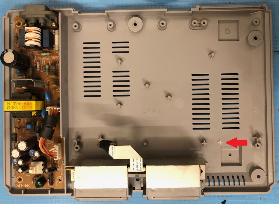
- The difficult part is now finished, but the lower part of the PS1 case still needs to be prepared.
Cut off the small plastic pin marked below in red.
This is necessary to prevent the flex cable from breaking during installation.
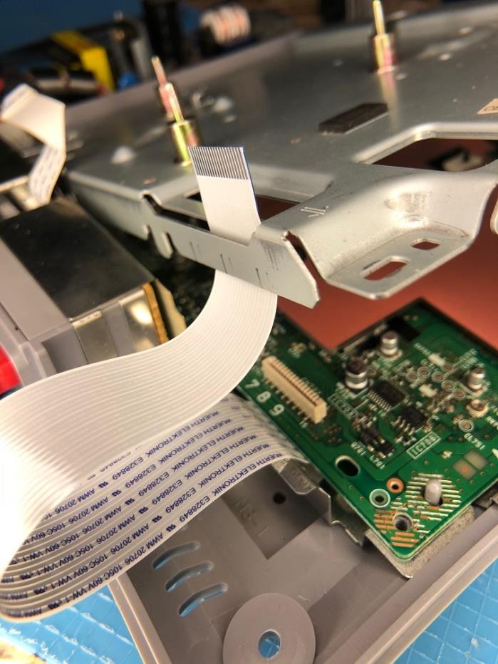
- Now you have to connect the flex cable to the cable holder on the QSB.
(blue side up) and close the cable holder.
When this is done you can lead the flex cable outside

- To ensure that the cable sits correctly route it through the slot on the top shield.
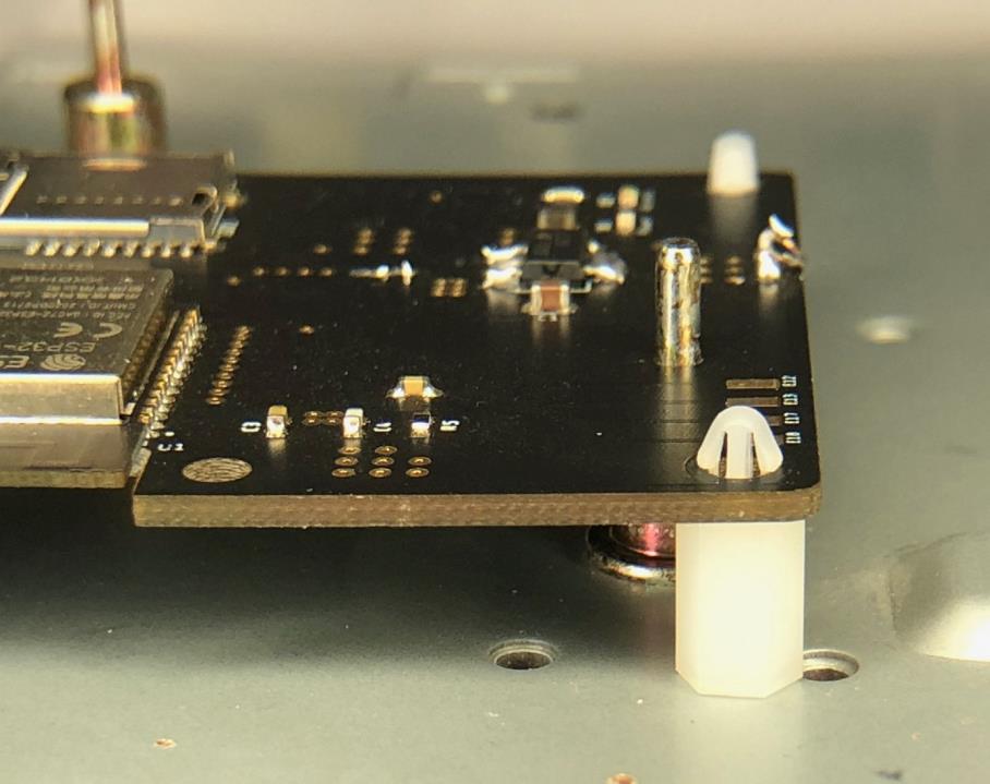
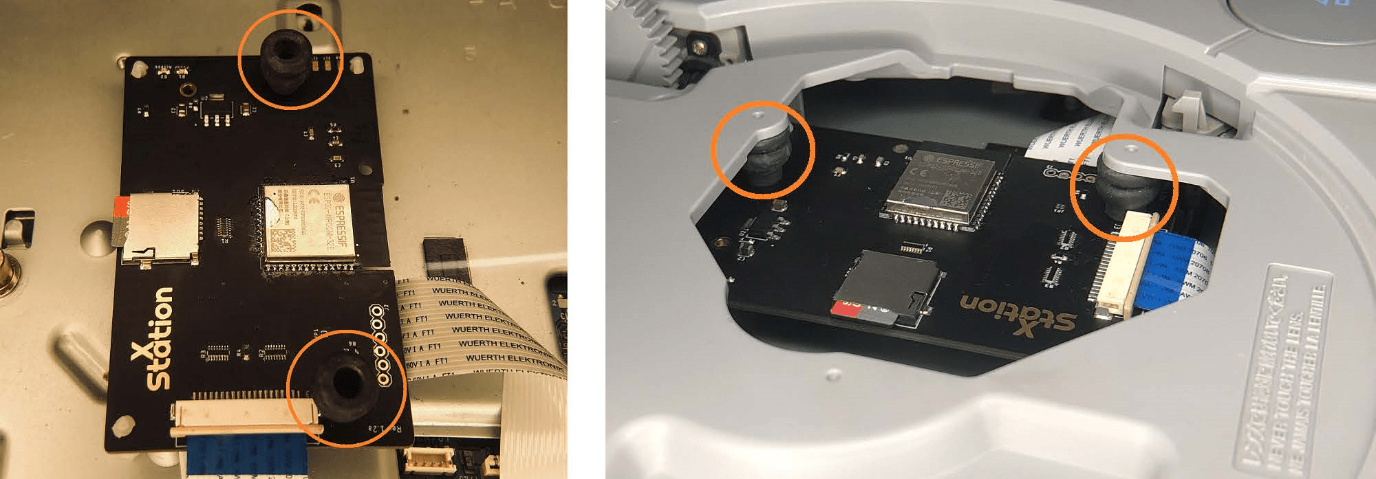
- Prepare the PCB and push all 3 spacers into the xStation board. If you look at it from above they can be found in:
- the lower right corner
- the upper right corner
- the upper left corner.
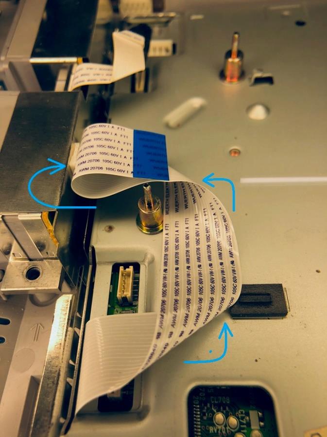
- Now grab the other side from the flex cable and carefully connect it to the cable holder on the xStation. When it is done you have to fold the flexcable a bit. Folding it like this is best:
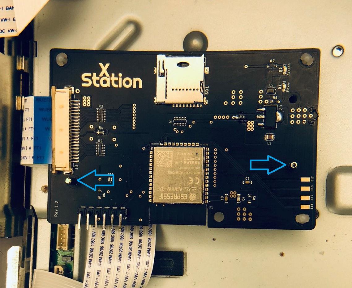
Mount the xStation on the posts of the original Disc Drive.
It should look like this:
When everything is ready, you have to reassemble the Playstation 1 in reverse
order.
A freshly installed xStation:
Recommended adaptation of PCB and SD card adapter
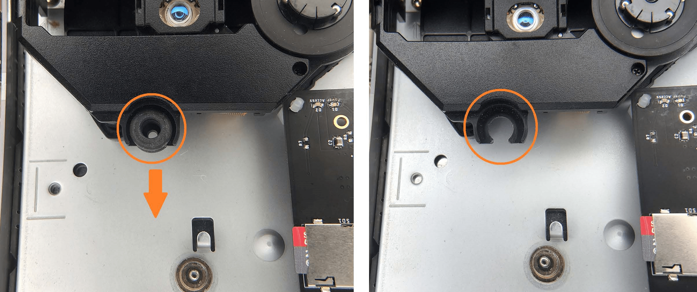
You can use the rubber spacer to clamp the xStation in place.
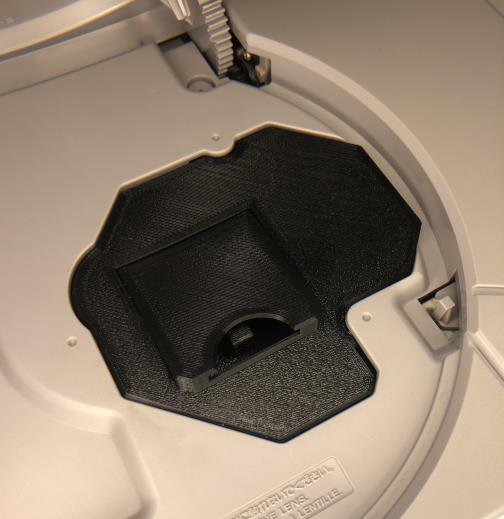
Use a 3D printed mount to fill the drive gap.
Initial Software Steps
- Format a microSD card to either exFAT or FAT32 using SD Card Formatter.
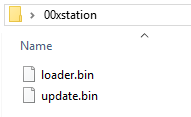
- Create a folder on your microSD card named “00xstation“ (without quotation marks), then download the latest update files and copy the files update.bin and loader.bin to the 00xstation folder.
The Latest Update can be found on our Firmware Page or the Official xStation Github.
From now on, your Playstation will boot right into the xStation loader!
Downloads
Credits
Original Author
Source
[wp_objects_pdf]