Last Updated: 5th March 2021
NESRGB
Installation Guide
Front Loading NES
Table of Contents
Preparation
Diagrams
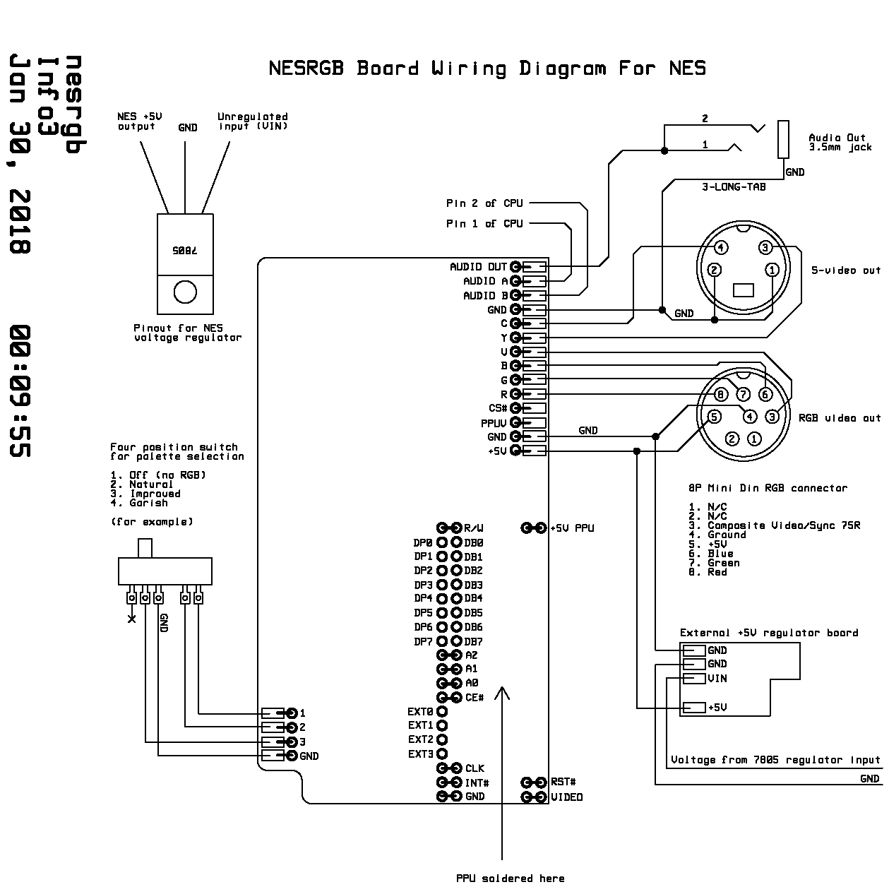
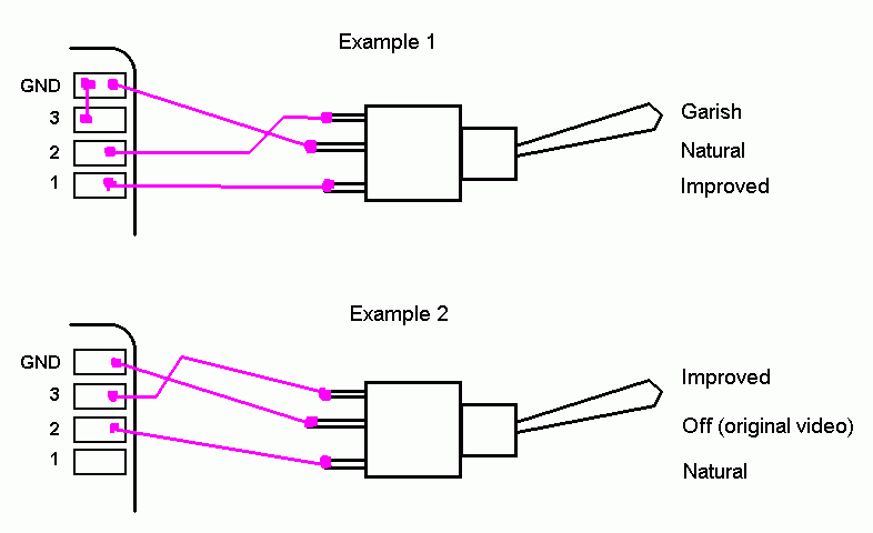
Print the Wiring Diagrams found below:
RGB Connector Information
A Note On Sync
There are two methods of transmitting sync information in use for 15 kHz RGB video. By far the most common is the use of composite video for sync which is used by SCART, Japanese RGB-21, pro monitors, and other television RGB systems. The other sync transmission method is TTL sync. This is mostly used in RGB monitors that were dedicated to a particular task. Arcade monitors, 1980s computer monitors (such as the Commodore 1084 series), and some specialized pro monitors fall into this category. Also, some VGA systems accept 15 kHz RGB video and these use the VGA sync method (separated TTL). Monitors that only accept TTL sync lack a particular circuit, known as a sync stripper, which is used for extracting the sync information from a composite video signal. It is possible to plug in an external sync stripper to make these monitors compatible with composite video sync.
When wiring the video connector you may choose either composite video (V), luma (Y), or TTL composite sync (CS#). All three will work equally well when displaying RGB video on a system expecting composite video sync. When connecting to a SCART system I recommend using composite video(V), as this gives you the option of viewing this if RGB is not available. The TTL composite sync (CS#) signal is compatible with systems expecting both composite video sync and TTL sync. I recommend this if you want the best compatibility with obscure video monitors. Note that this is only true of my products. Normally, TTL sync (from an arcade PCB for example) is not guaranteed to work correctly when connected to a video input.
Other notes
Audio is on a separate connector to prevent video noise from getting into the signal. This completely solves the ‘buzzing sound on RGB SCART’ problem that many people with cheap SCART cables have experienced.
Reasons for the decision.
I preferred to use an RGB connection standard that was already used by somebody else. The connection must use a connector that is widely available, easy to mount, and is not dedicated to a particular purpose (such as a USB connector is, for example). It is also unacceptable to require additional components connected to the video signal. This was often done by Sega and other game console manufacturers to reduce the cost of their game consoles at the expense of the cables.
I started by looking through the list of Game Console RGB SCART Cable Diagrams. So many use proprietary connectors or require extra components! The only one to meet the criteria is the Neo Geo AES, a console known for its variable RGB video quality. Some people have used Sub-D connector in these circumstances… I considered this but the D shaped connector is quite difficult to mount. VGA connector is not suitable because the signals are not compatible with VGA and this will cause confusion. SCART connectors are too large and funny shaped…
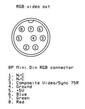
I settled on the connection from the Micomsoft XRGB-mini Framemeister. This uses a small 8 pin mini din connector for audio and RGB video. Sync on composite video (75 ohms terminated). It’s basically SCART/Jap RGB-21 with all the extraneous pins removed. The only change I make is to leave off the audio pins. The signals audio and video signals should go through separate cables so that they don’t interfere with one another. This is the simple solution to the audio interference problem. The alternative would be to use special cables that keep the signals separate along their length. This would make pre-made cables significantly more difficult to make (and hence more expensive) with little added benefit. People are used to plugging in multiple connectors at once anyway.
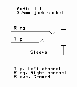
The choice of a 3.5mm jack socket instead of a pair of phono (RCA) connectors was mostly an aesthetic one. The mini din connectors that I supply are small and do not protrude much. The 3.5mm jack protrudes the same amount and takes up very little panel space. This is important for space-constrained consoles such as the Famicom.
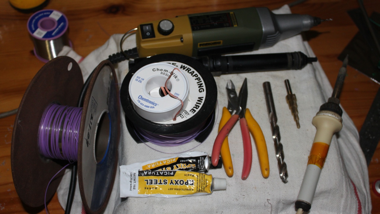
Tools
Some tools and materials are required
- Soldering iron and leaded solder wire
- Insulated copper wire
- Solder sucker and solder wick (both are necessary)
- Two part epoxy glue
- Pliers and cutters
- Drill
- Large twist drill bit (something like 9 or 10 mm is ideal)
- Step drill bit (for making 6mm and 12mm holes)
- Screwdrivers
- High speed cutting tool (optional)
Desoldering the PPU
More info on desoldering the PPU is here on a separate page.
Removing the PPU is the most difficult part of the installation. Here I describe a method using solder wick and a solder sucker. If you have access to a desoldering iron I recommend using it instead as it is by far the easiest way to remove ICs from plated-through boards. Alternatively, I have heard that a heat gun or SMT rework station can be used to successfully remove the PPU, but be careful not to overheat the board this way.
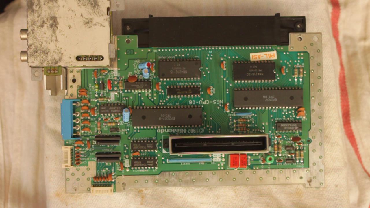
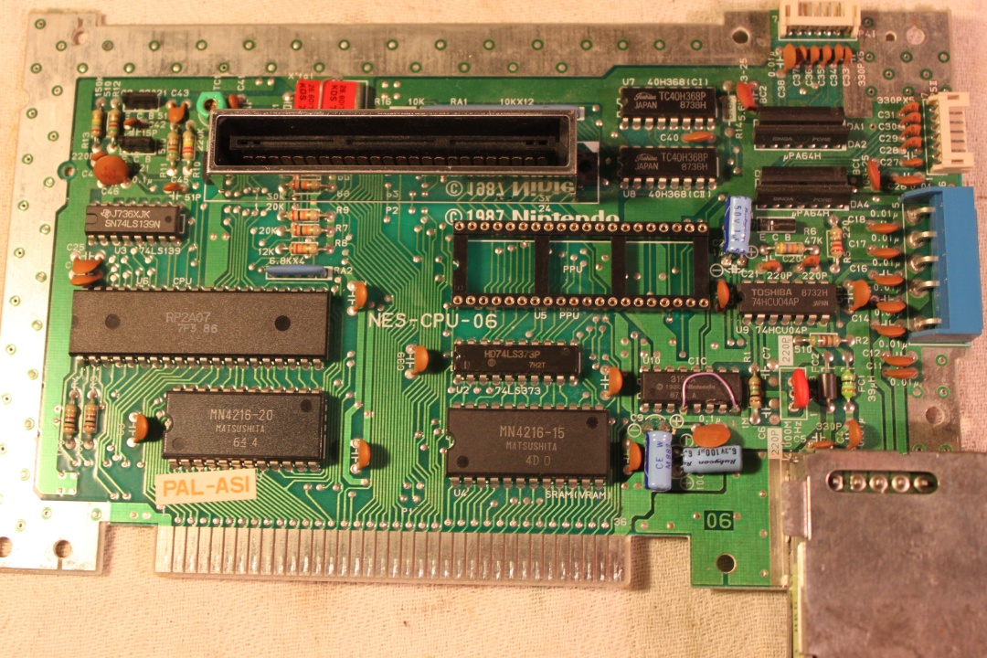
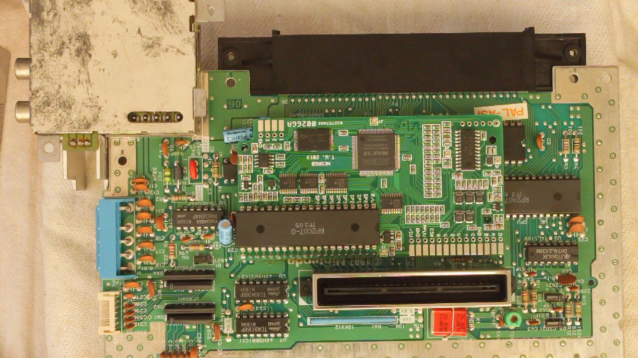
1. Pull apart NES and retrieve motherboard from inside. Identify the PPU chip. The PAL version is marked RP2C07, the NTSC version is RP2C02. It has to come out without damage to the chip or the board. The board is double-sided with through-plated holes.
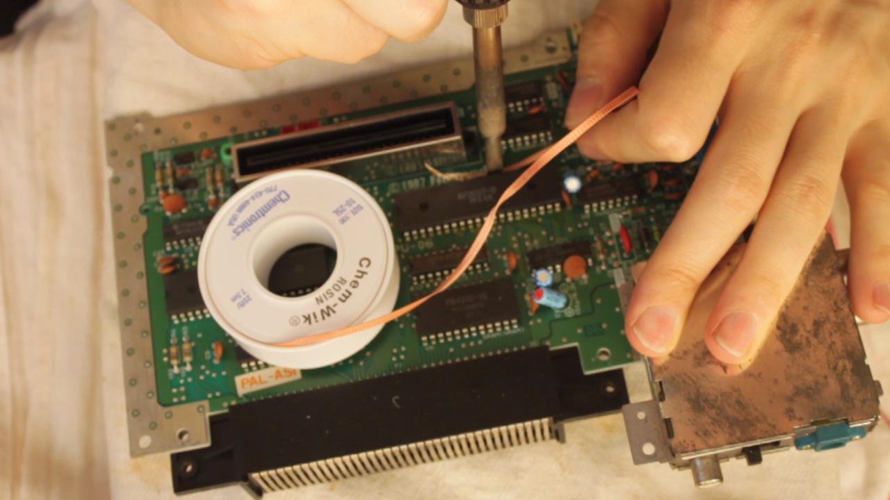
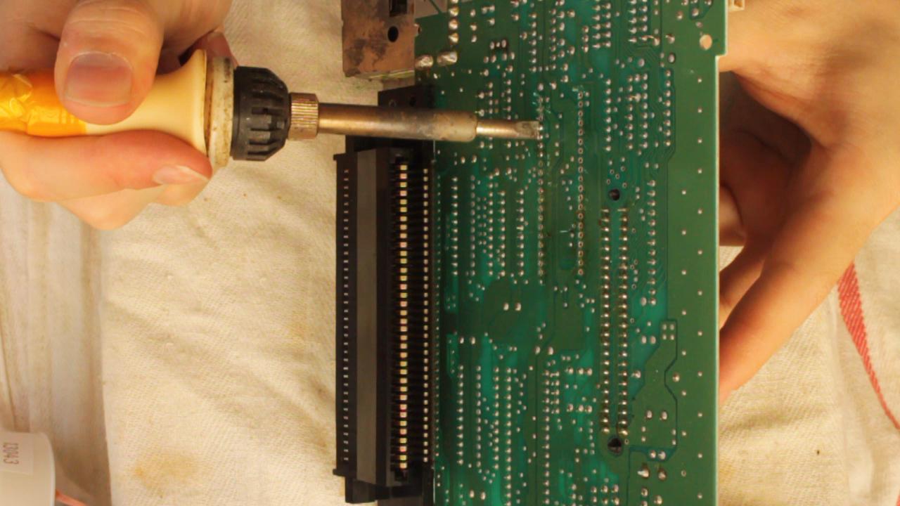
Use solder wick to remove solder from the legs of the PPU on the top side of the board.
Use a solder sucker to remove the remaining solder from the bottom of the board. You will probably find it difficult to remove the solder from pins 14-17. That’s because they are connected to a large copper plane which conducts the heat away from the solder joint. Skip these for pins for now. Remove the solder from all the others. Test that each pin moves freely in the hole before moving to the next one.
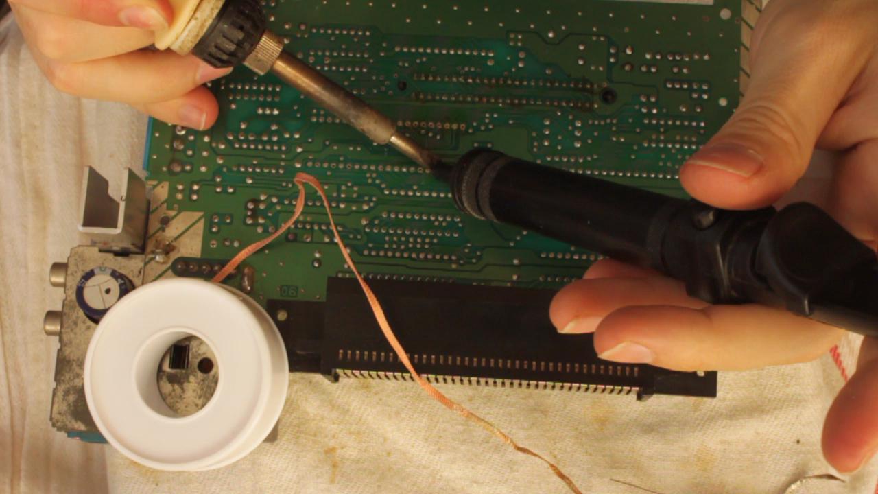
Add lots of fresh solder to pins 14-17. Heat them all up at once and pull out the PPU while the joints are molten. Be careful not to damage the pins of the PPU. Do not use excessive force. If another pin does not want to move, add extra solder then remove it again with solder wick/sucker.
Prepare NESRGB board
** Note that the type of IC sockets and switch included with the kit has changed since this installation guide was first created. The older style is still visible in some pictures.
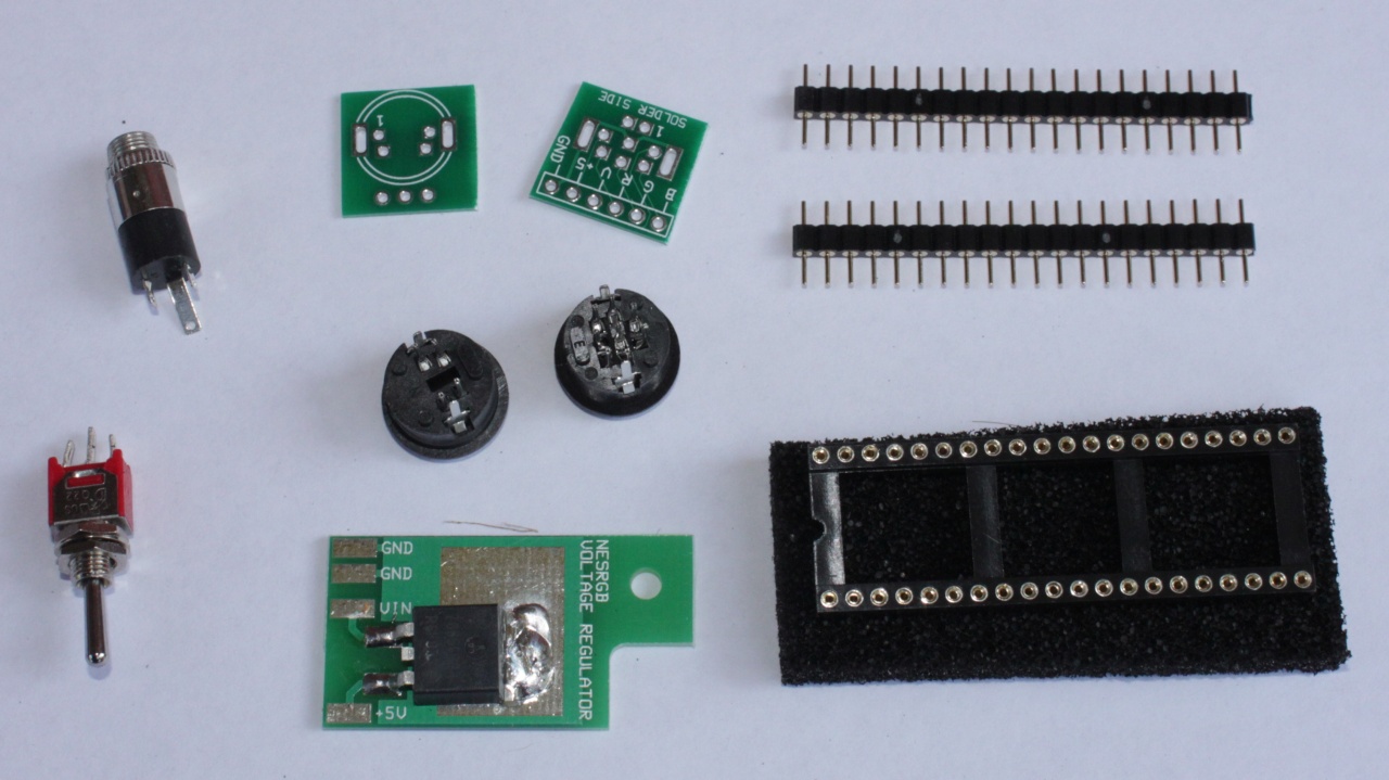
1. Open package and check everything.
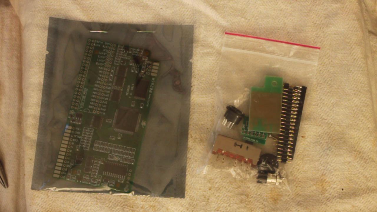
The following parts are included with the kit for the front loading NES.
- toggle switch (on-off-on) for palette selection
- audio connector 3.5mm jack socket
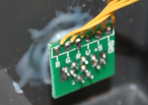
- s-video connector with pin label board
- RGB video connector with pin label board
- 40 pin DIP round pin IC socket
- pair of 20 pins round pin strip
- voltage regulator board
- NESRGB board
2. Insert 40 pin socket into NES motherboard. Solder.
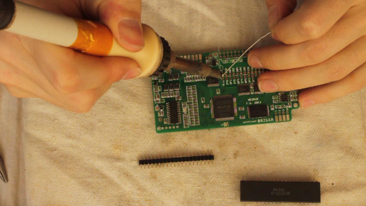
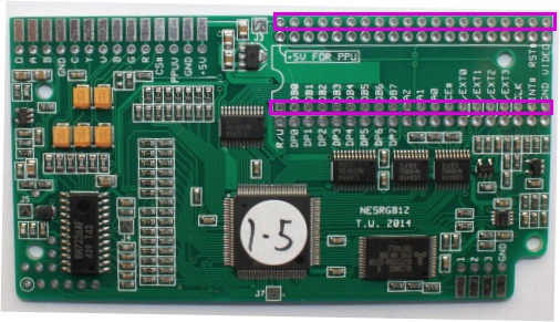
3. Solder the two strips of round pin headers onto the NESRGB board. The best way (not pictured) is to insert the pin headers into the socket on the motherboard, then place the NESRGB board on top and solder in place. The way the pins will be perfectly aligned. Be careful to solder the pins into the correct position.
4. Straighten PPU pins with pliers if necessary.
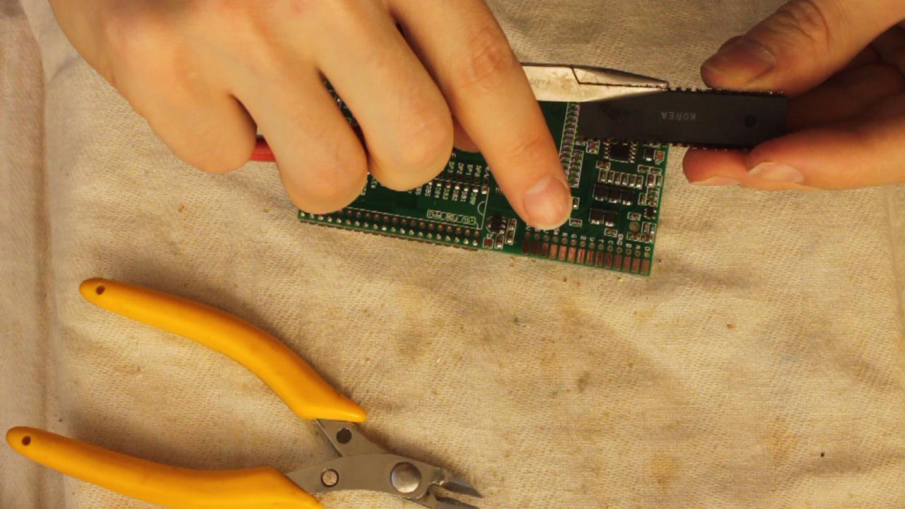
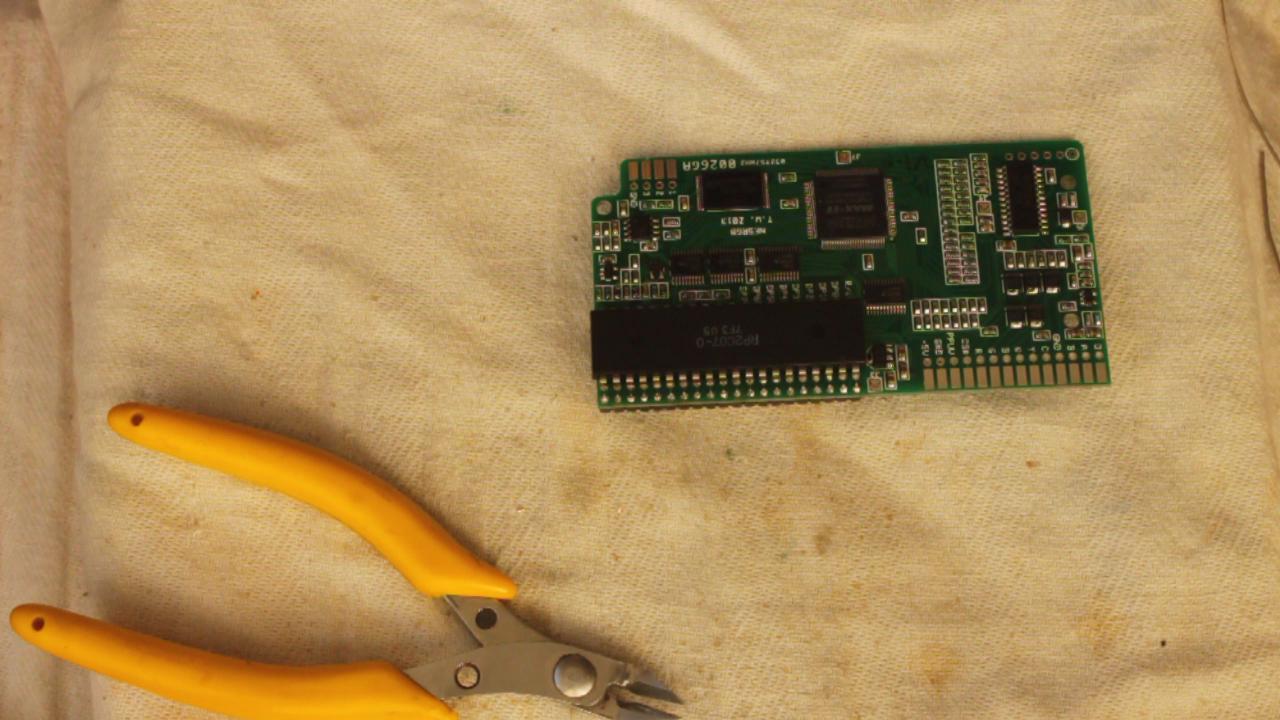
5. Insert PPU and solder into place on the board. Do not put the PPU into a socket as there is not enough space (height) available for it to fit. Double-check to make sure the PPU is in the right way around!
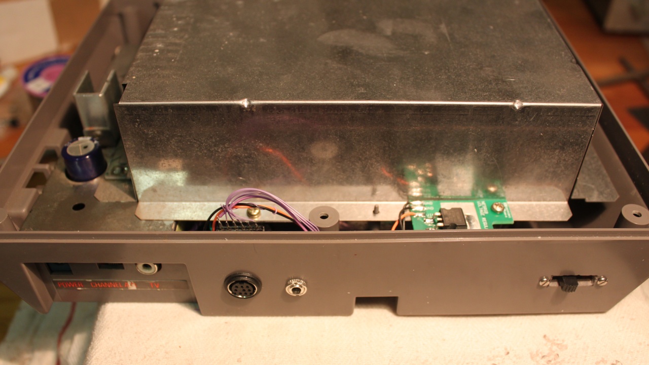
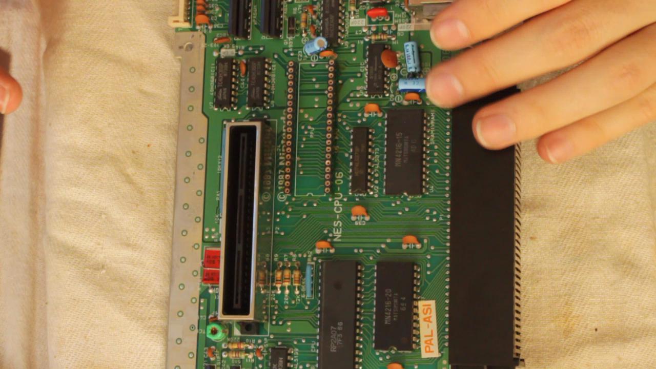
6. Attempt to insert NESRGB board into the socket on the motherboard, only to find there are some capacitors blocking the way.
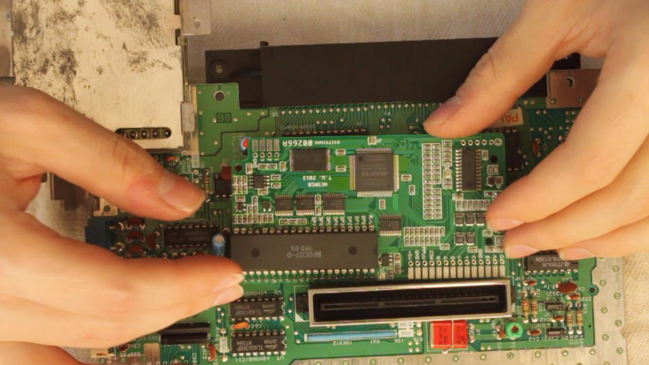
7. In this particular motherboard revision the two blue electrolytic capacitors (located at my middle finger) are in the way. Heat up their solder joints and pull them out a bit then lay them flat against the motherboard.
8. Insert the NESRGB board uninhibited.
If you have an NTSC version NES you should solder jumper J5. If you have a PAL version NES, you need to solder jumpers J4 and J7.
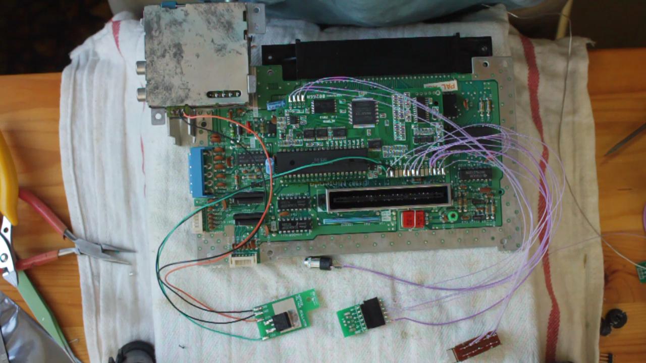
Solder wires
1. Cut, strip, and tin lots of wires to a length of 250mm. One length fits all. Use thicker wires for power and ground connections.
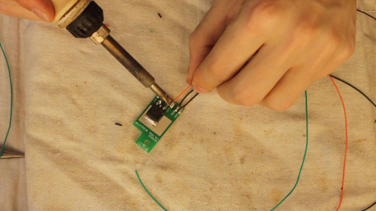
2. Solder wires to the voltage regulator. Check the wiring diagram for details. Both ground wires must be soldered – one is for the NESRGB board and the other is for the connection to the internal NES voltage regulator.
3. Solder wires to the switch, audio, and video connector board. Do not solder the video connector to the video connector board yet.
4. Wire up everything according to the wiring diagram. Don’t forget to set the solder jumpers as required. The wiring diagram shows the wiring for a four-position palette switch.
Kits are now supplied with a small SPDT on-off-on toggle switch. Wiring options are as follows.
Mechanical
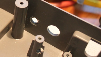
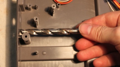
1. Drill a 6mm hole for the audio connector. The audio connector is a 3.5mm jack socket which is designed to be mounted on a 2mm thick panel. The walls of the NES are approx. 3mm thick so in order to mount it, you must recess the hole. Simply use a larger twist drill bit and turn with your hand a few times.
2. Drill a 12mm hole for the video connector. You must use a step drill bit for this hole. Plan the location of your holes carefully to avoid damaging the screw boss while drilling.
3. Glue the video connector into position in the 12mm hole with epoxy. Once the glue has set solder the video connector board on. Make sure the pin label board is soldered on the right way around. The connector goes on the side with the circle.
4. Mount the voltage regulator board in a convenient location. Use a high-speed cutting tool to cut a hole for the palette switch (optional).