Last Updated: 5th March 2021
PU-7
Table of Contents
Switch Board Installation
Information
The Switch Board is required in order for PSIO to work correctly. The reason behind it is that Sony never provided direct access to the CD-ROM CPU on the Parallel I/O bus. In our case, access to the CDDA and XA interrupt lines. What the Switch Board does is it actually switches the required data lines and forwards them through to the PSIO cartridge. The Switch Board also allows PSIO to drive the CD-ROM directly and give us complete control over it.
Keep in mind that the Switch Board is completely invisible to the PlayStation.
That means, when your PSIO cartridge is unplugged and not in use, your PlayStation returns back to normal operation. The CD-ROM drive will work as it normally would, and you will also be able to use Game Shark/Action Replay cartridges like normal.
If you have a Modchip installed in your PlayStation, the Switch Board and Modchip will work fine side by side with each other. Remember, the Switch Board is invisible to the PlayStation.
Installation
First off, you will require some tools:
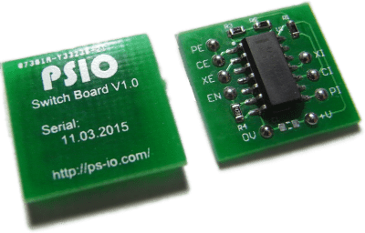
- Switch Board (included with your PSIO cartridge purchase),
- Kynar Wire (included with your PSIO cartridge purchase),
- Soldering Iron (use a good tip!),
- Solder (preferably flux cored 60/40),
- Flux (optional),
- 10x Magnification Jewellers Microscope/Loop (optional),
- Phillips Screwdriver,
- A Multimeter (for Continuity Testing),
- A sharp ‘hobby’ knife (EG: X-Acto), and
- Scissors.
First off, you will need to disassemble your PlayStation 1. However, before you start to disassemble your console, you must ensure that your PlayStation 1 is completely isolated and unplugged from all connections, including most importantly, the main power cable (AC).
Ensure that you have taken out any CD-ROM’s in the drive and have put them away safely.
Once you have ensured your console is isolated and unplugged, turn it over, and unscrew all of the screws on the back. Then, whilst holding the sides with two hands, flip the console over. You can then lift off the top shell to expose the internal components.
The next step is to remove the CD-ROM assembly system. There are two cables that connect the drive to the mainboard. One is a delicate ribbon cable, and the other is a pair of twisted core wire. Both cables simply unplug by pulling on them, but be careful not to tear the ribbon cable.
Depending on your PlayStation model, each system disassembles differently from here on in, but the next step is essentially removing the metal chassis.
Once you have removed all the screws from the steel chassis, it should now lift of freely, exposing the bare mainboard.
Next, begin removing the rest of the screws holding the mainboard to the bottom half of the plastic case. Keep in mind that when reassembling your console that the screws go back in a certain method as some are left blank for the steel chassis to mount though.
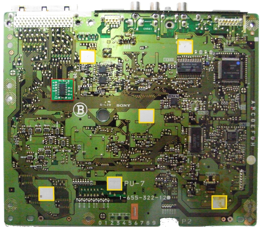
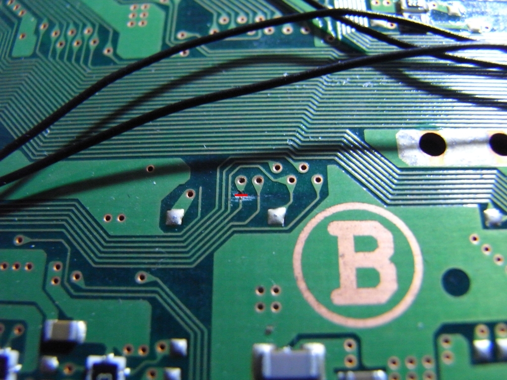
Once you have the board out of the console, flip it over to show the bottom layer of the PCB (as seen in the image below). Next, carefully peel off the double-sided tape on the back of the Switch Board, and adhere it to the seen location marked in red below. Do not place it anywhere besides the specified area, and ensure that you have the Switch Board orientated in the correct position before securing it. Ensure the Switch Board is adhered well and it will not fall off and short itself against the steel/metal chassis that is housed under the PlayStation mainboard.
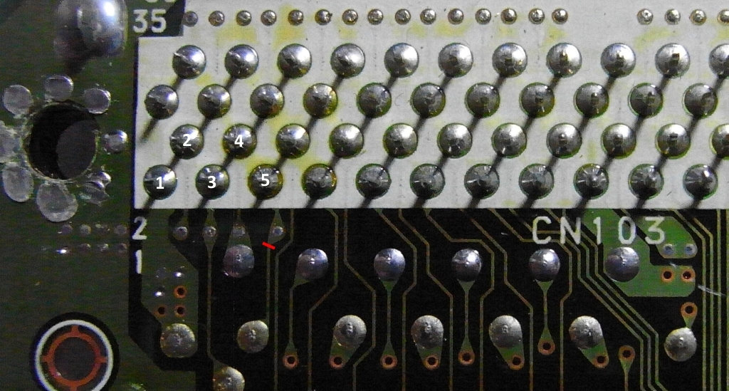
The next stage is to cut a trace on the Parallel Port.
It is known as Pin 5, and it is a Ground pin, but it must be used instead for the Switch Boards “EN” (Enable) line.
Cut through the marked point in red to isolate Pin 5.
Solder Pin 5 to the “EN” line on the Switch Board.
The next step is to solder the “CD MECH INT” and “CD MECH CS” lines.
Note that there are no trace cuts in this photo.
You can see the points marked in yellow for where to solder.

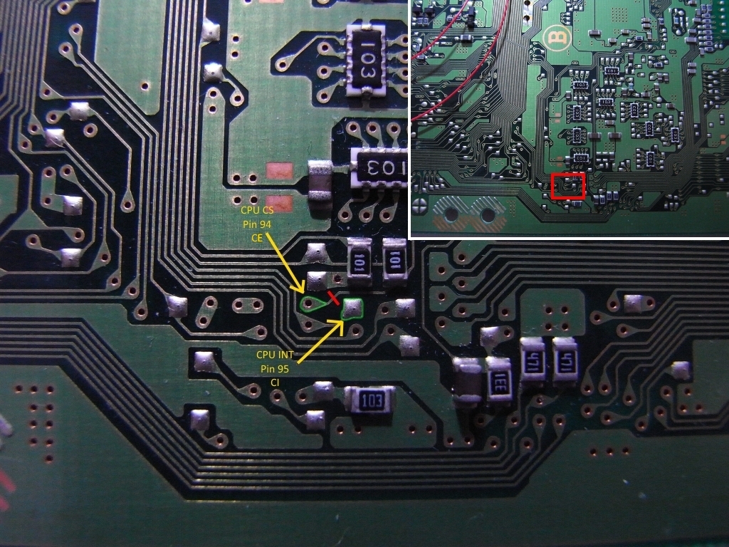
The next two trace cuts are more difficult. They are known as the “CPU INT” and “CD MECH CS” lines (marked in red).
They might take you a while at first to locate on the mainboard, but take your time and don’t rush.
Cut the ‘CPU CS’ trace where the red line is placed.
The outlined areas marked in green are where you solder. However, the soldermask on the ‘CPU CS’ via must be carefully scraped away to expose the copper.
The ‘CPU INT’ has a pad conveniently placed and does not require the soldermask to be scraped on its via.
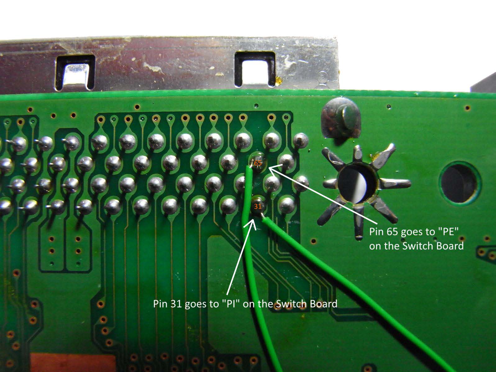
The next two (2) pins to solder are pins 65 and 31 on the parallel port.
There are no trace cuts needed in this step.
Pin 65 goes to “PE” on the Switch Board.
Pin 31 goes to “PI” on the Switch Board.
Lastly, the power connections are required. The first one is the 3.3V (3V3) rail.
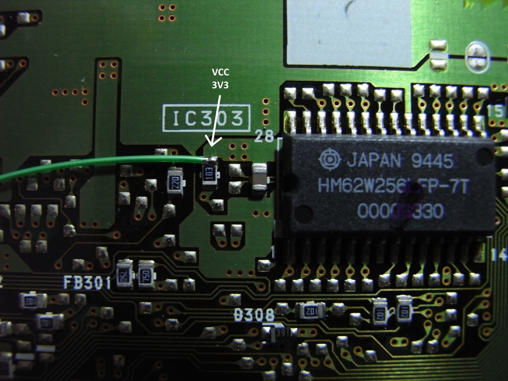
And secondly, the “Ground (Gnd)” connection.
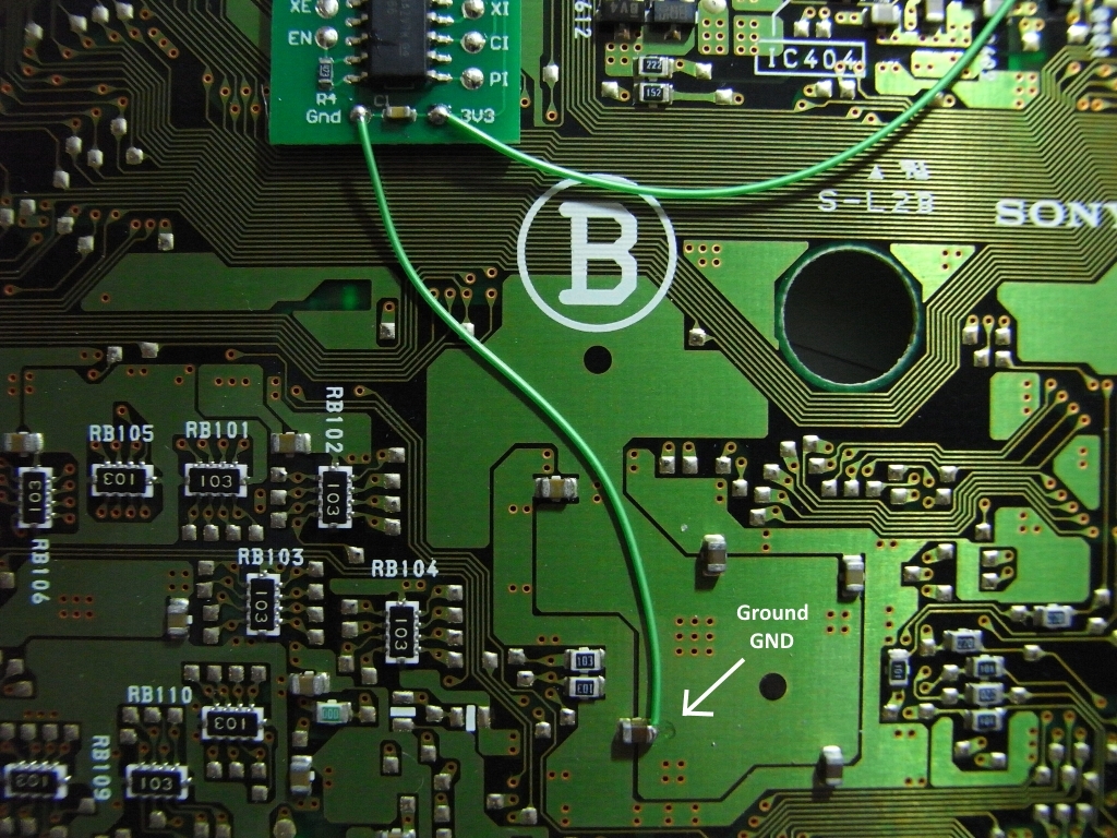
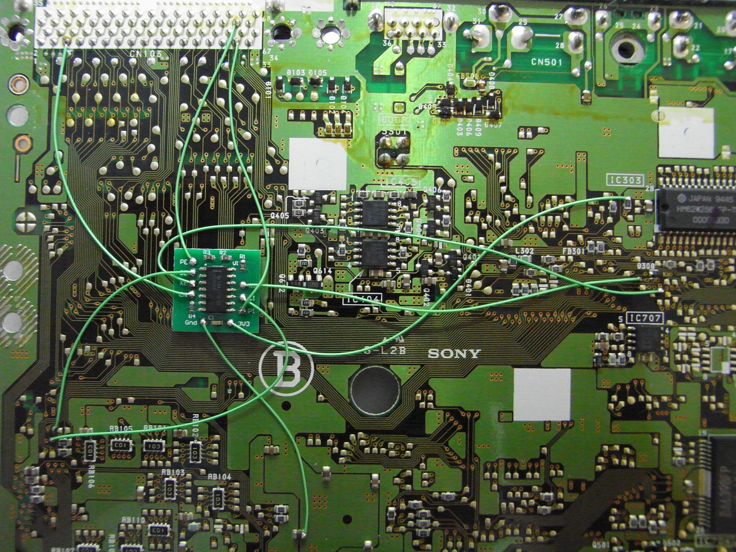
Congratulations! You have successfully modified your PlayStation with a Switch Board. This is what your installation should look like:
As a warning, we suggest that you check for shorts on the Ground (Gnd) and 3.3 Volt (Vcc) rails using your Multi-meter (continuity tester). If you do not check and there is a short, you will blow a fuse on your PlayStation mainboard, and it will be required to be replaced.
With that being said, you may now re-assemble your console and test CD-ROM loading without a PSIO cartridge plugged in, and then testing PSIO by having the cartridge plugged in.
When booting with the PSIO cartridge however, ensure that an SD Card with “MENU.SYS” is present, otherwise you will have no way of seeing a visual output from your PSIO cartridge indicating that it is in fact booting and working.
Remember to always turn off your PlayStation before unplugging and inserting a PSIO cartridge. Don’t forget to also adhere the included “Switch Board Sticker” to the back of your PlayStation case.
Specifications
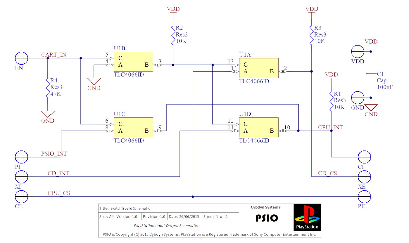
The Switch Board is open source, and simply consists of a 4066 bilateral switch and a few passive components. The schematic may be seen below.
If you require a replacement or would like to buy more Switch Boards for installation in more PlayStation consoles to use PSIO on, please see our ‘Store’ to purchase more completed boards.