
Last Updated: 5th March 2021
OneChip PM 41 (2) Diagram
Introduction
Towards the end of the SCPH-10x PSone production Sony revised the board slightly and released the PM-41 (2) board. This page covers the installation diagram for installing a ONEchip chip into the PM-41 (2).
If your board has PM-41 printed on it then you should follow the PM-41 guide instead.
Board components and fuse locations
Here are a couple of photos of the PM-41 (2) board. If you click on them they’ll open in a much higher resolution format so you can zoom in on the details. This first image shows the front of the board (marked with the letter A).

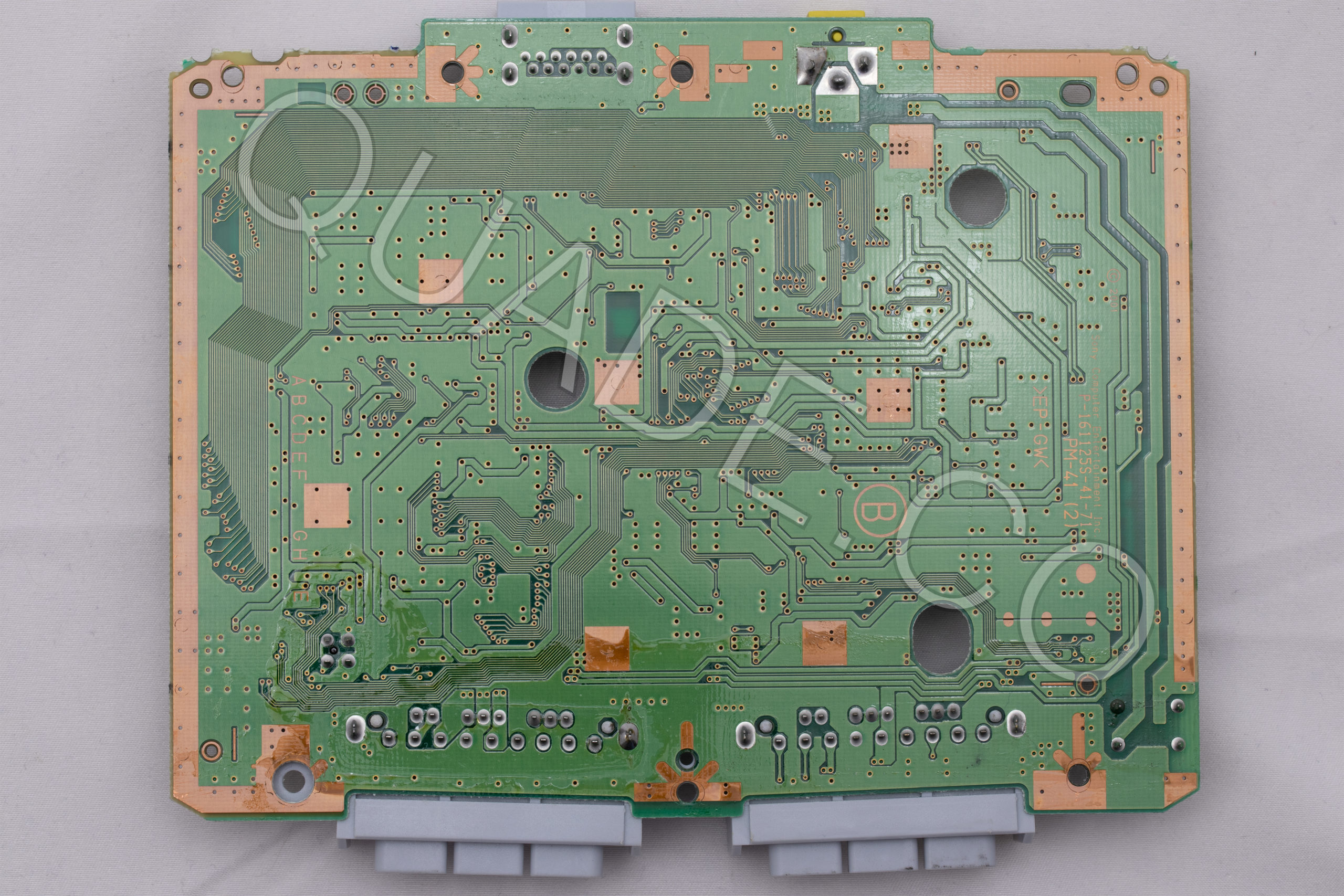
This second image shows the back of the board (marked with the letter B).
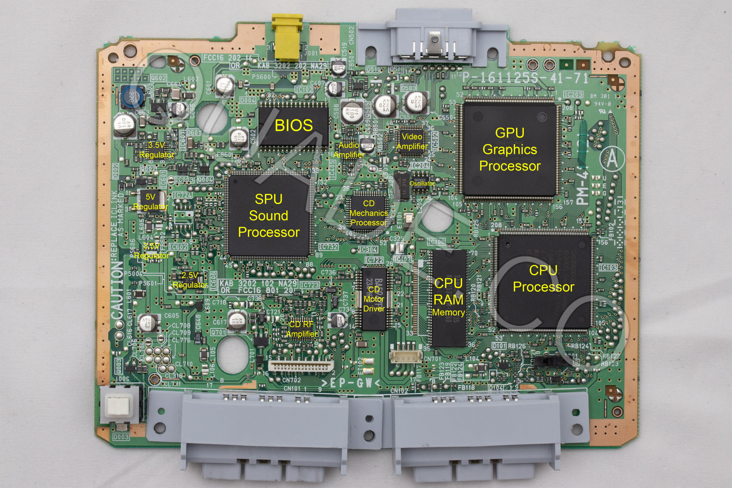
Below is that picture of the front of the board again, but this time it has labels on all of the major board components. This can be useful if you are debugging an issue on the system. For example if your video output is bad you might want to try replacing the capacitors near the video amplifier.
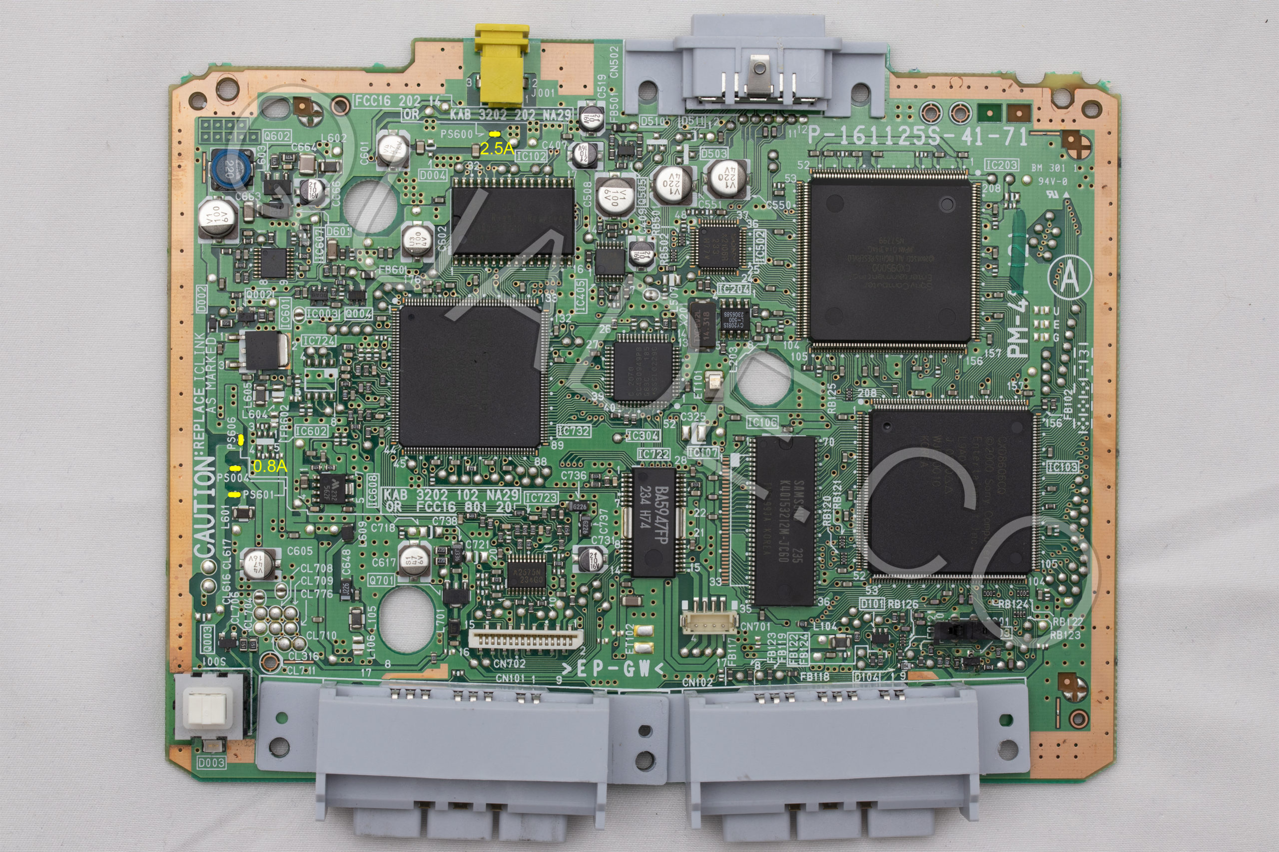
Another common issue people run into is blown fuses. Below is a diagram showing the locations of all of the fuses on the PM-41 (2) board. They are highlighted in yellow, with the fuse value nearby.
Installation Diagram
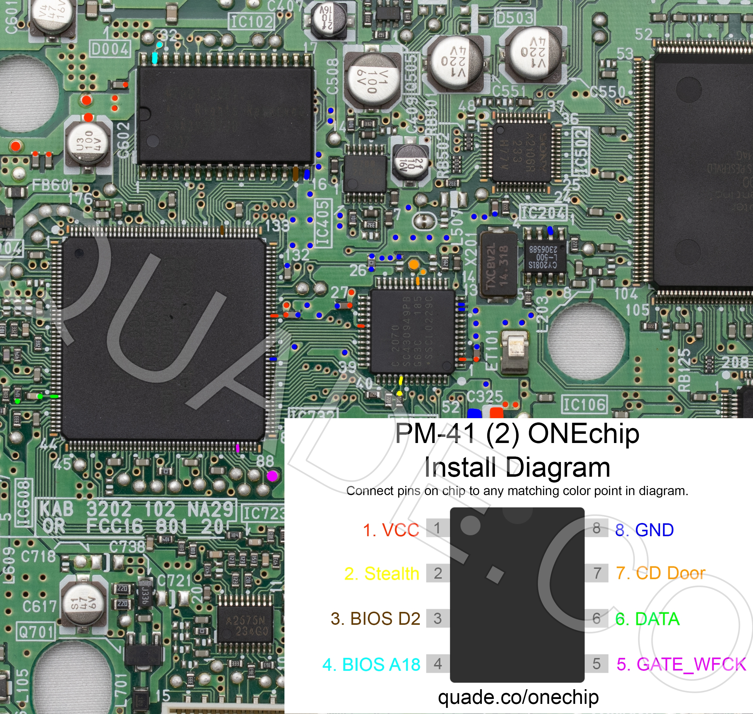
Above is the installation diagram. Just match each colored pin label in the diagram with any matching colored point on the board. Click on the image for a higher resolution version. I recommend placing the modchip on top of the CD mechanics processor chip.
I have created additional diagrams primarily for colorblind people. They show one point at a time in a single color (there is a set in red, green, and blue). Because they show the entire board they may reveal more alternative points for each pin. Click on the links below to reveal the sets of images.
I’m creating these new diagrams for each PS1 board revision working from newest revision to oldest revision. It’s going to take some time, but should hopefully be more helpful than the older diagrams I had on here before.
Installation tips
Here are some tips I have for you when you are soldering your chip into the PM-41 (2).
- Cut your wires to be as short and direct as possible.
- Pin 2, and 6 can be tricky. Don’t push on the components with your soldering iron or they might get knocked off the board. You can use tweezers to carefully solder them back on one side at a time, the orientation doesn’t matter.
- Make sure the wires you are soldering don’t come into contact with other components or legs of chips.