Last Updated: 5th March 2021
NESRGB
Buggy Releases
4th of March 2019
The de-jitter feature of the new version 2.0 hardware causes sync instability under some circumstances in NTSC consoles. It looks like horizontal screen wobbling and may get better or worse as the console warms up. It affects boards with version 2.1 software which were those sold from 17th to 28th of February 2019. If you have these symptoms, I recommend updating to version 2.2 firmware.
18th of October 2017
Most boards sold between December 2016 and October 2017 have a fake voltage regulator IC fitted.
How to identify
Genuine
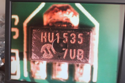
The genuine part has clear printing and a circular mould marking in the centre of its package; the text depends on manufacture date.
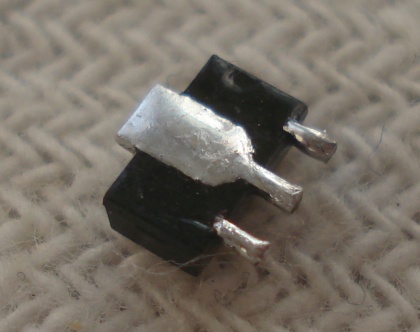
Fake
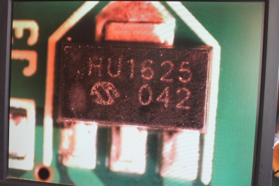
The fake part has poor quality printing, no mould marking; the text always reads HU1625 042.
The part number is MCP1703T-3302E/MB manufactured by Microchip. The fake is probably a Chinese LM1117 or similar (e.g. AMS1117-3.3).
The fake part is not a direct equivalent for the genuine one. The genuine part is designed for stability with a ceramic output capacitor in the 2-10 uF range. The fake part is probably meant to have an electrolytic or tantalum output capacitor in the 10-100 uF range. In some cases, the fake voltage regulator will oscillate.
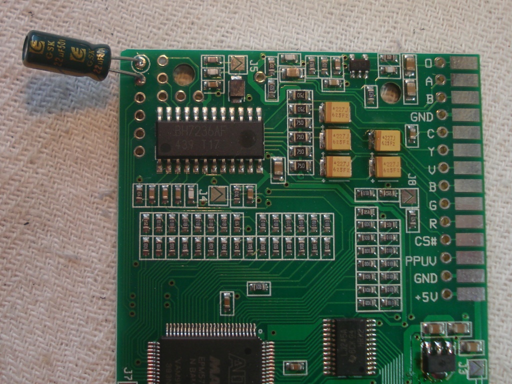
Solution #1
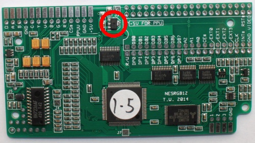
Add an extra electrolytic capacitor between the 3.3V power rail and ground. This should make the fake regulator operate correctly and prevent oscillation. The easiest place to solder the capacitor is on the programming header. The cap’s positive leg should be soldered to pin 1 (encircled), which is 3.3V; the negative leg is soldered to pin 2 which is ground. The capacitor should be either a 22 uF or 47 uF type – any voltage rating will do.
Solution #2
The second, more difficult solution is to replace the fake voltage regulator with a genuine part. To remove it from the PCB, you can use a hot air rework station or a soldering iron. The method for the soldering iron is to add extra solder to each of the three pins, then hold the iron in such a way as the tip is making contact with all three pins simultaneously. The thermal connection between the centre pin and the tab will eventually cause the solder to melt. Then the part will slide off the board.