Last Updated: 5th March 2021
NESRGB
Installation Guide
Famicom Twin

Table of Contents
Tools and materials required:
- Soldering iron and leaded solder wire
- Insulated copper ‘hook up’ wire. It’s better to use wire that is thin and easy to work with.
- Solder sucker or desoldering iron to remove the PPU.
- Pliers and cutters
- Drill with a step drill bit which goes up to 12mm (optional)
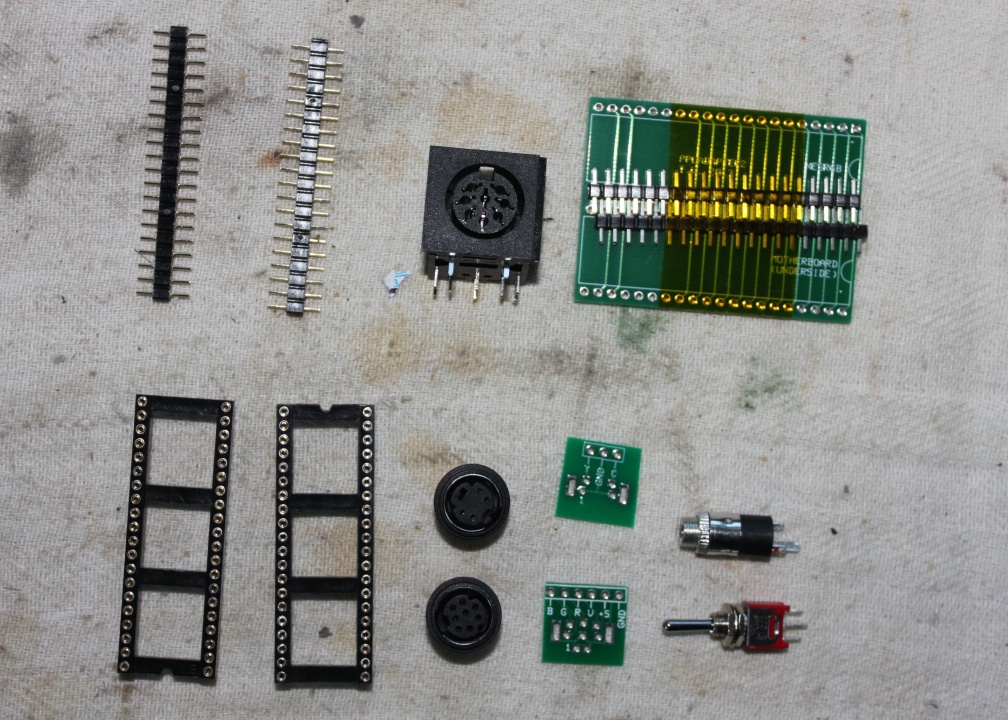
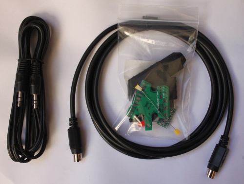
The following parts are included with the kit for the Famicom AV.
- toggle switch (on-off-on) for palette selection
- audio connector 3.5mm jack socket
- s-video 4p connector with pin label board (not used in this guide)
- RGB 8p video connector with pin label board
- pair of 40 pin DIP round pin IC sockets
- pair of 20 pins round pin strip
- adapter board #2 for Famicom Twin
- pair of 20 pin square pin strip (taped to adapter board)
- 8 pin DIN PCB mount connector
- NESRGB board (not pictured)
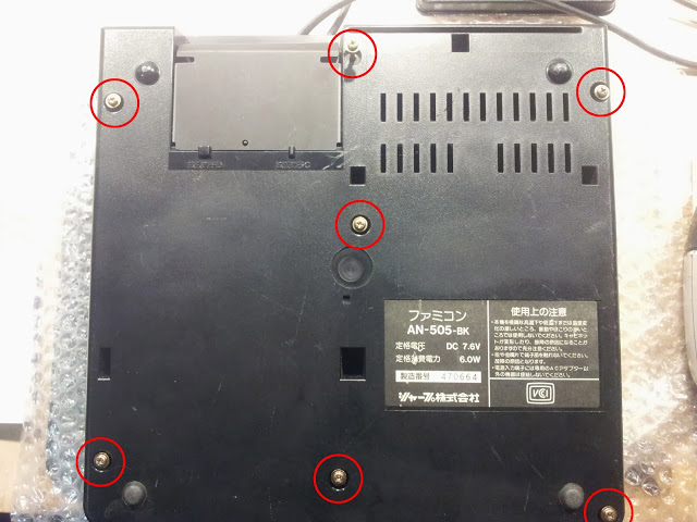
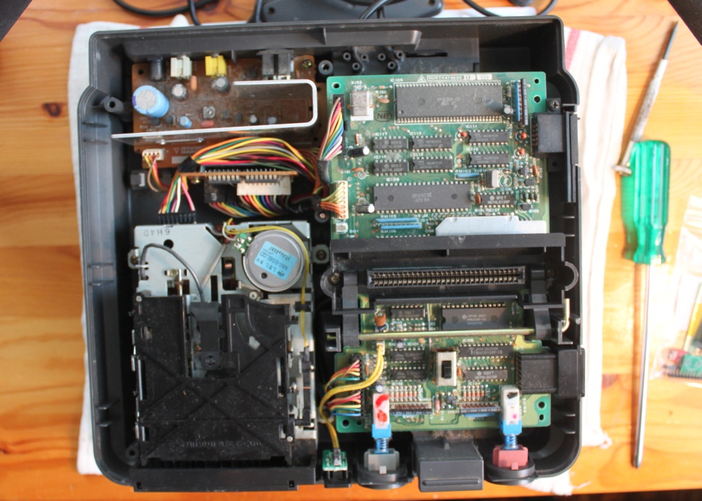
Open the Famicom Twin by removing the seven long screws from the bottom.
Remove the motherboard from the unit by first unplugging the connectors from the left-hand side, then removing the screws and rod from the eject mechanism.
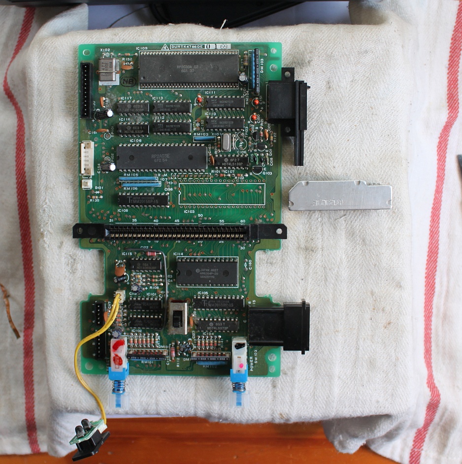
Identify and desolder the PPU. This can be tricky because the motherboard’s holes are plated through. Please read the article here: Desoldering the PPU.
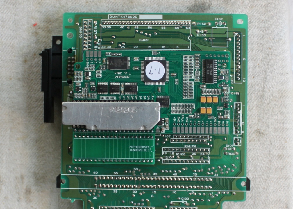
The PPU in my unit has a heat sink glued over the top marked R1292CE. This is a bit unusual – most of the time, it will not be covered.
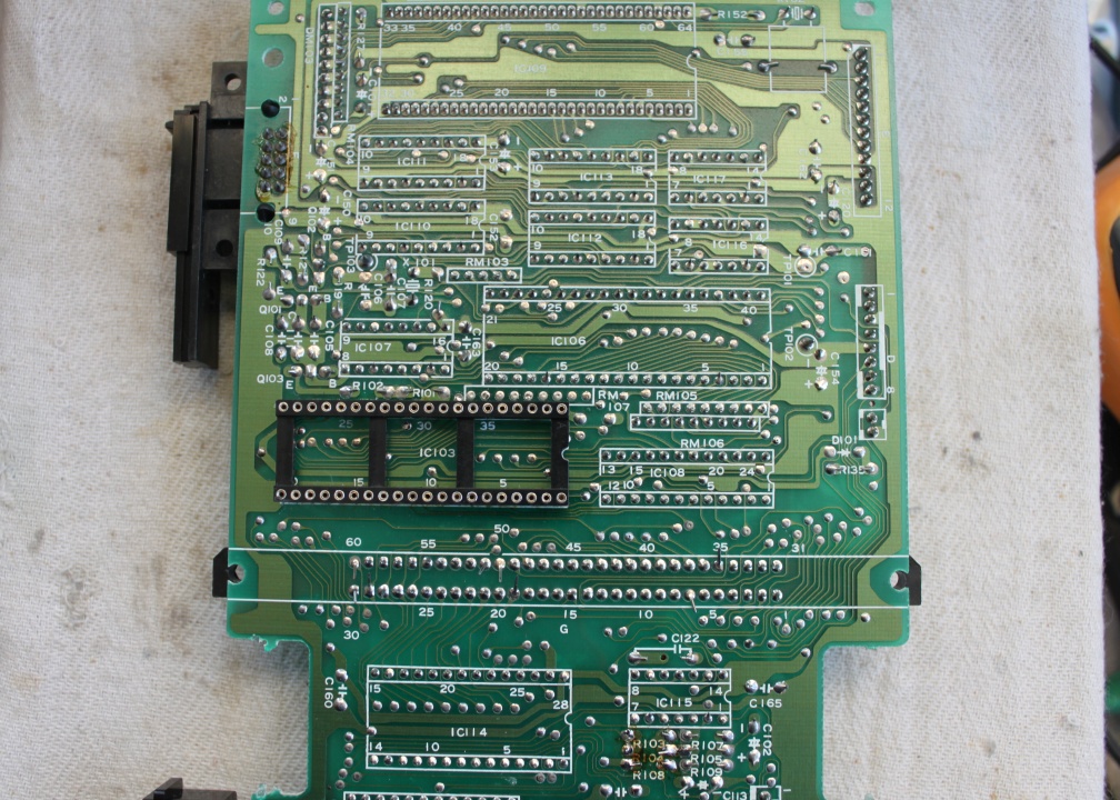
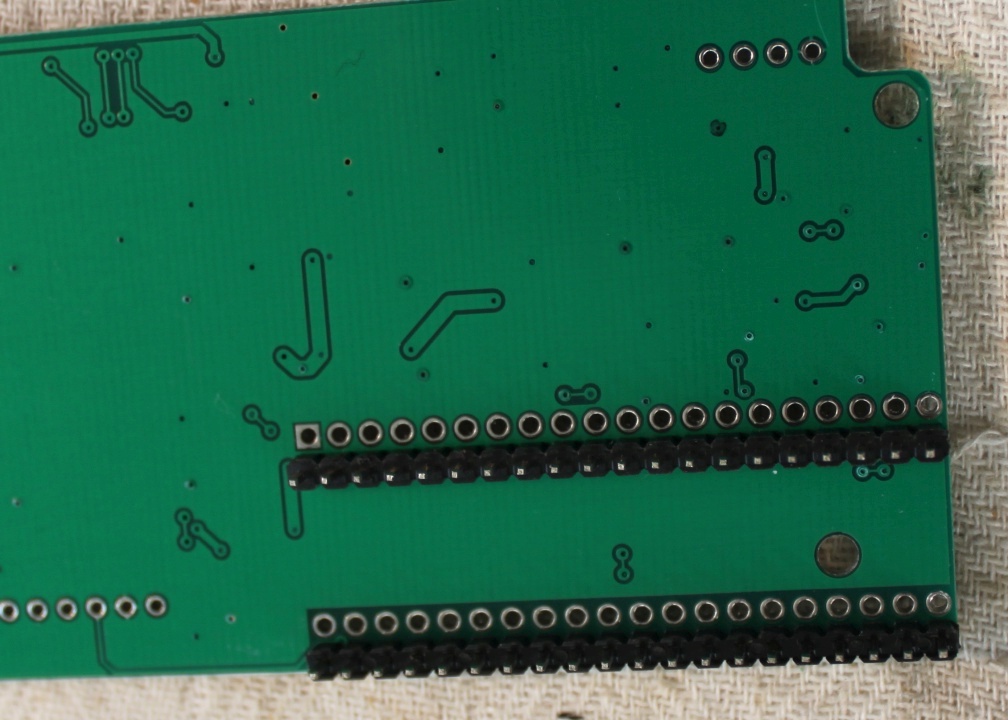
Turn the motherboard over to the solder side. The NESRGB will be installed underneath the motherboard as there is more space there.
Place the socket in the empty PPU location, then place the two strips of round pin strip into the socket.
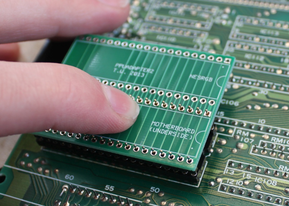
With a finger on the adapter board, solder the adapter board pins in place. Then turn the motherboard upside down and solder the 40 pin IC socket on the bottom. This way, the pins will be straight and aligned correctly.
Remove the NESRGB board from its packaging.
Insert the square pin strip into the underside of the NESRGB board. Double-check they are in the correct place then solder them in.
Insert the other 40 pin IC socket into the NESRGB board and solder it in place.
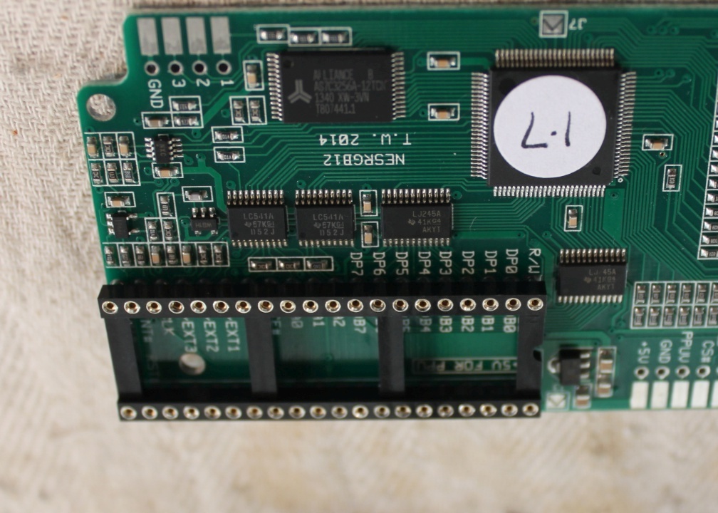
Insert the NESRGB board into the adapter board into the position marked ‘NESRGB’. Solder it in place.
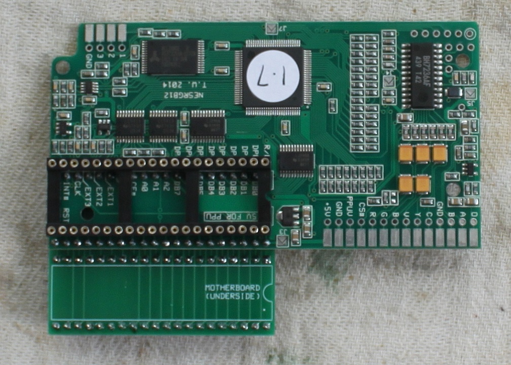
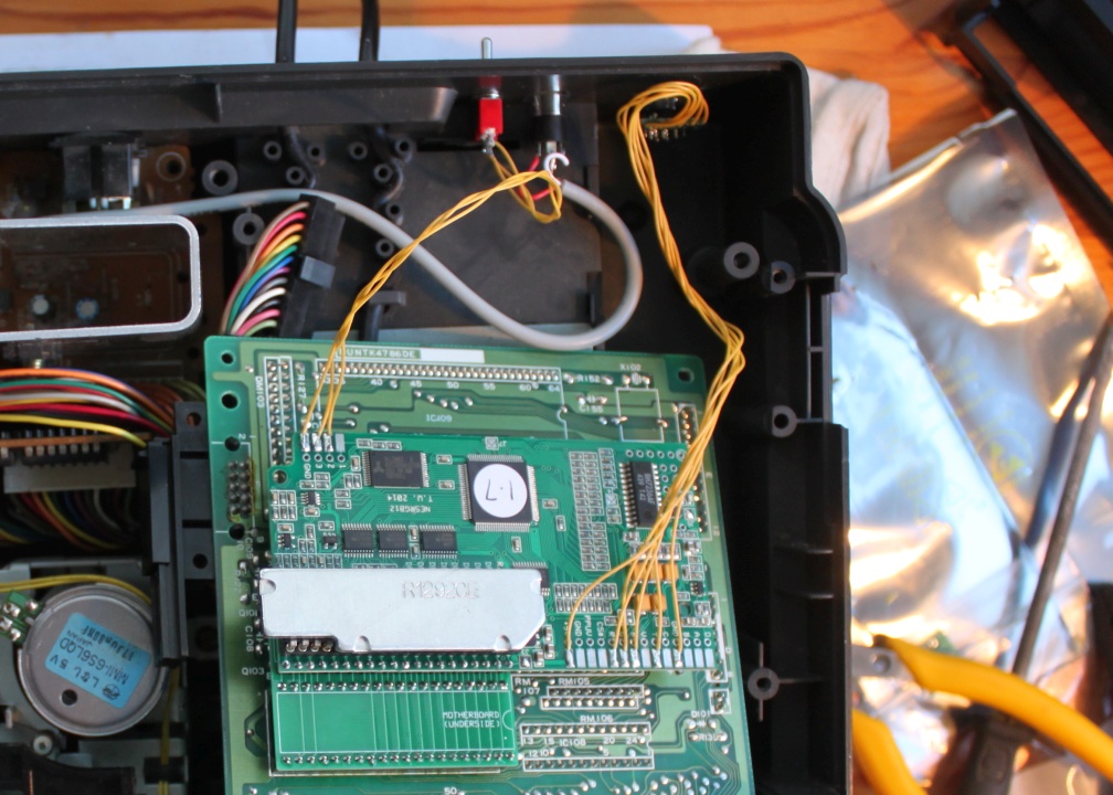
Pop the PPU into the socket on the NESRGB board and insert the finished NESRGB assembly into the socket on the underside of the Famicom Twin motherboard. Solder jumpers J3 (for power) and J5 (NTSC video).
The next step is to drill holes to mount the audio/video connectors and palette switch. The 8 pin mini-DIN connector has the same pin arrangement as compatible with this RGB SCART cable.
The audio connects through a separate cable to ensure audio there is no interference from the video signals. If you prefer to have audio and video run through one cable, you can connect the audio signals to pins 1 and 2 of the mini-DIN.
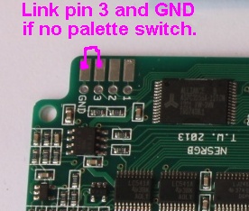
The NESRGB board features three palettes to choose from. This feature is optional if you do not want a palette switch, bridge pin 3 and GND to permanently select the natural palette.
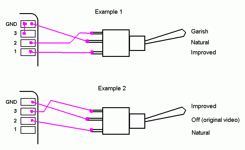
There are multiple ways to wire this switch depending on the desired result.
Kits are now supplied with a small SPDT on-off-on toggle switch. Wiring options are as follows.
To mount the 8p mini-DIN first drill a 12mm hole with a step drill bit (do not use a twist drill bit). Insert the connector into the hole and glue into place. You should use epoxy glue; this is a glue that comes in two parts which are mixed together. Once the glue is set, place the pin label board over the pins and solder it into place.
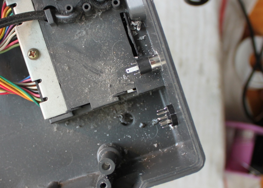
To mount the 3.5mm stereo jack socket. Drill a 6mm hole with the step drill bit or a twist drill bit. The wall of the case is a bit thick for this connector. To fix this insert a large (10-12mm) into the inside of the hole and turn by hand until about 1mm of plastic is removed. The hole will look like the one in the photo to the left.
Drill a 5mm hole with a twist drill bit to mount the palette switch.
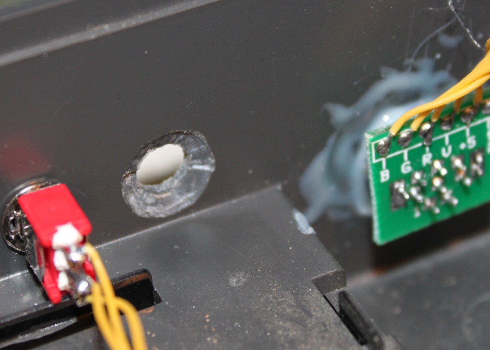
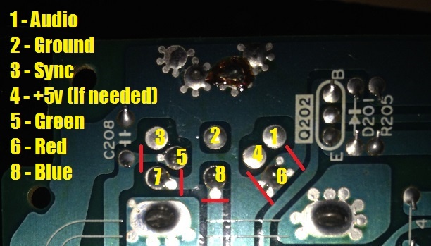
Connect the wires. The 8p mini-DIN connector is wired to the NESRGB board. The signals Blue, Green, Red, Video (composite), +5V, and Ground. If you look closely at this picture, you’ll see I have wired Y (luma) in place of Video (composite) as a sync signal. I recommend this as composite video as sync has been reported to cause some video interference under some circumstances.
The audio is connected to the signal from the original audio output jack. The 3.5mm socket is a stereo connection to connect the audio signal to both left and right pins. It’s best to use shielded wire if you have some.
The palette switch is wired to the palette pins if required.
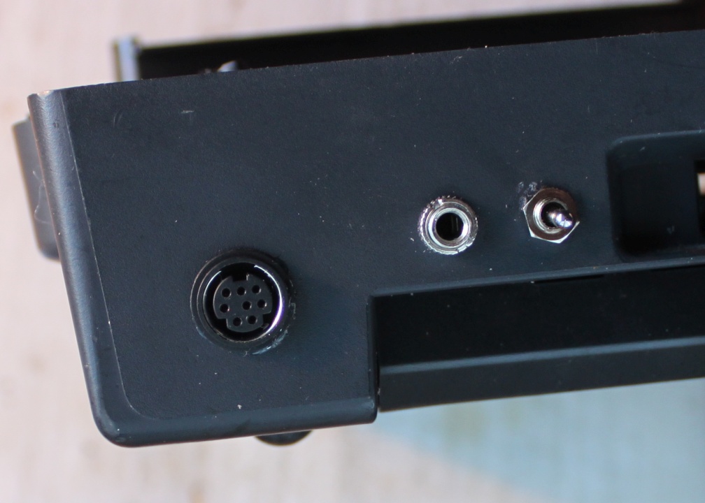
Video / audio connectors, palette switch external view. Perhaps you can find better locations that I did, but take care to avoid getting in the way of the controller port bays in the lid.
Install the motherboard back into the console, put the screws back in, finished!
RGB connection alternative, discreet method.
Some may wish to connect the new RGB cable without making any modification to the shell.
The Famicom Twin features a connection on the back for connecting an external RF modulator. It is possible to repurpose this connection for RGB video/audio.
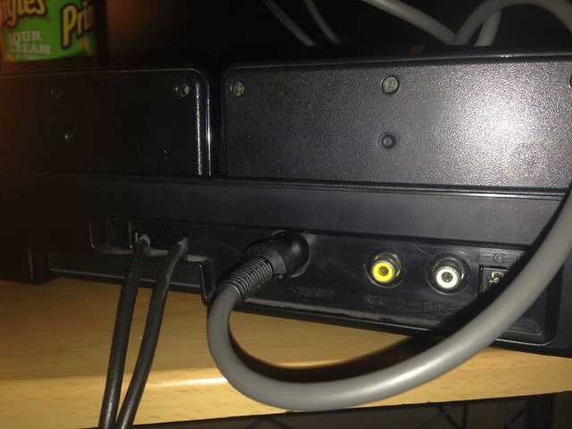
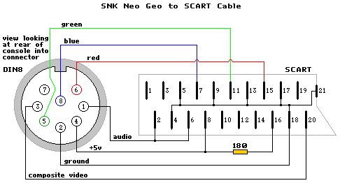
I recommend following the pin arrangement as the SNK Neo-Geo consoles as they also make use of an 8 pin DIN connection.
Some models of Famicom Twin are missing pins on the RF connector. From September 2014 onwards I will include in the kit a replacement socket which is fully pinned.
To the left is a diagram showing tracks that must be cut to accommodate the new pin configuration. The diagram of a Neo Geo SCART cable can be found below.
Addendum – Famicom Twin audio circuit modifications (advanced).
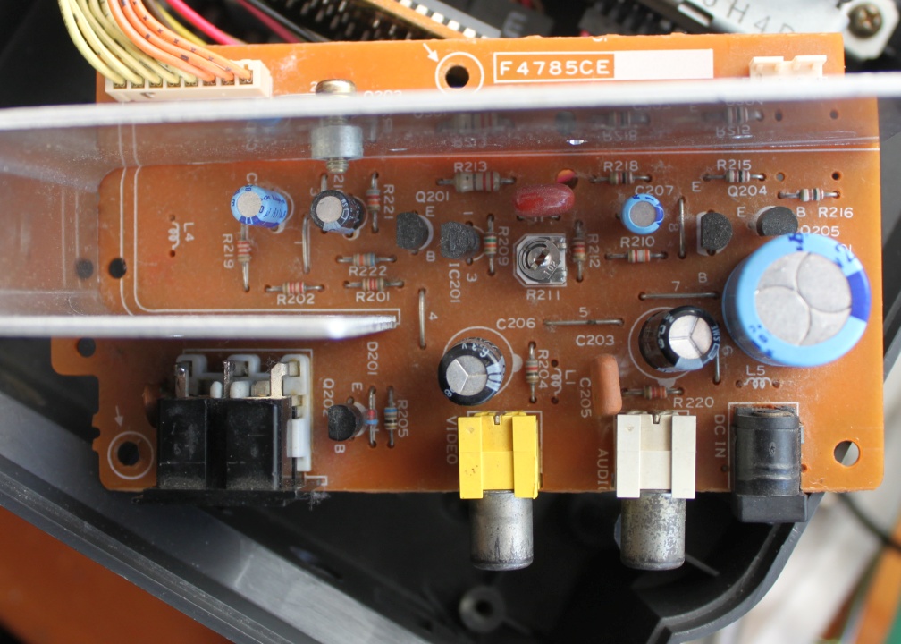
My Famicom Twin was a fairly early model, made mid-late 1986 going by the date codes on the parts. I have traced out the audio circuit of my unit.
Skip to PDF content
Note that there may have been changes/manufacturing variations on models made later. I encountered two problems with the audio.
Audio output level is too low.
The level is lower than the NES and other game consoles. This is fixed by changing the value of resistor R201 on the audio board. The original resistor is 8k2. Replacing it with a 2k2 value will increase the audio level on the output.
Disk games sound bad.
The title screen music from Hikari Shinwa: Parutena no Kagami (Kid Icarus) sounded like this:
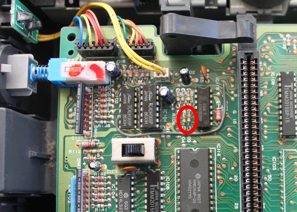
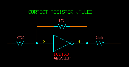
The extra FDS sound channel is too loud and drowns out the regular Famicom sound. The problem is two resistors in the FDS audio section have been swapped around. They are R104 2M2 and R103 1M2. This is a mistake. These two resistors should be swapped, so it is R104 1M2 and R103 2M2.
Once the resistors are in the correct position, it now sounds like this: